
Project · Octave
The Scrabbler
The Scrabbler is the circuit from the old Ampeg™ Scramber stompbox. (any trademarks used here do not belong to General Guitar Gadgets). (Once) rare and always exciting, this beast can mangle your sound, provide a unique blended distortion or anything in between. It has a "Balance" control feature that lets you blend in the dry guitar sound for lots of tonal variation. Some notable players include Jorma Kaukonen of Jefferson Airplane, John Cippolina of Quicksilver Messenger Service and Jim McCarty of Cactus.
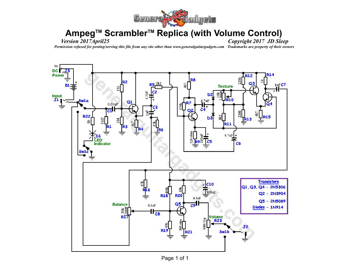
We have project instructions for the original and more importantly we have a revised circuit that add a volume control and some added boost. The revisions do not alter the original sound at all, jut makes it a little louder with control on the loudness.
Project files
Everything you need to build it
Scrabbler Ready-For-Transfer Printed Circuit Board Layout - For use only if you are a complete DIY person who wants to etch and drill your own PCB. Otherwise, we recommend you ignore this PCB mask and buy the Ready-to-Solder Printed Circuit Board or Complete Kit.
Scrambler™ Project History File
Scrabbler Ready-For-Transfer Printed Circuit Board Layout - For use only if you are a complete DIY person who wants to etch and drill your own PCB. Otherwise, we recommend you ignore this PCB mask and buy the Ready-to-Solder Printed Circuit Board or Complete Kit.
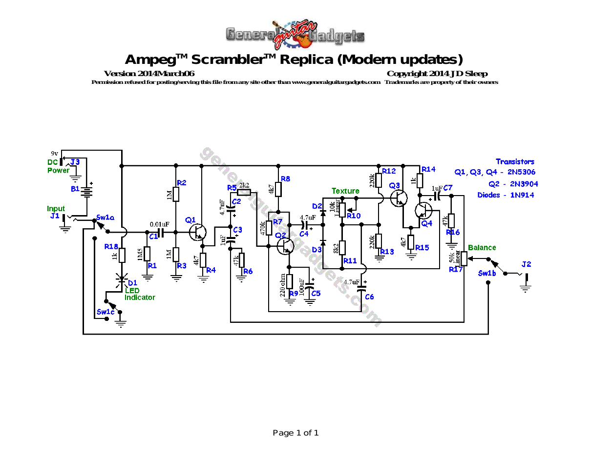
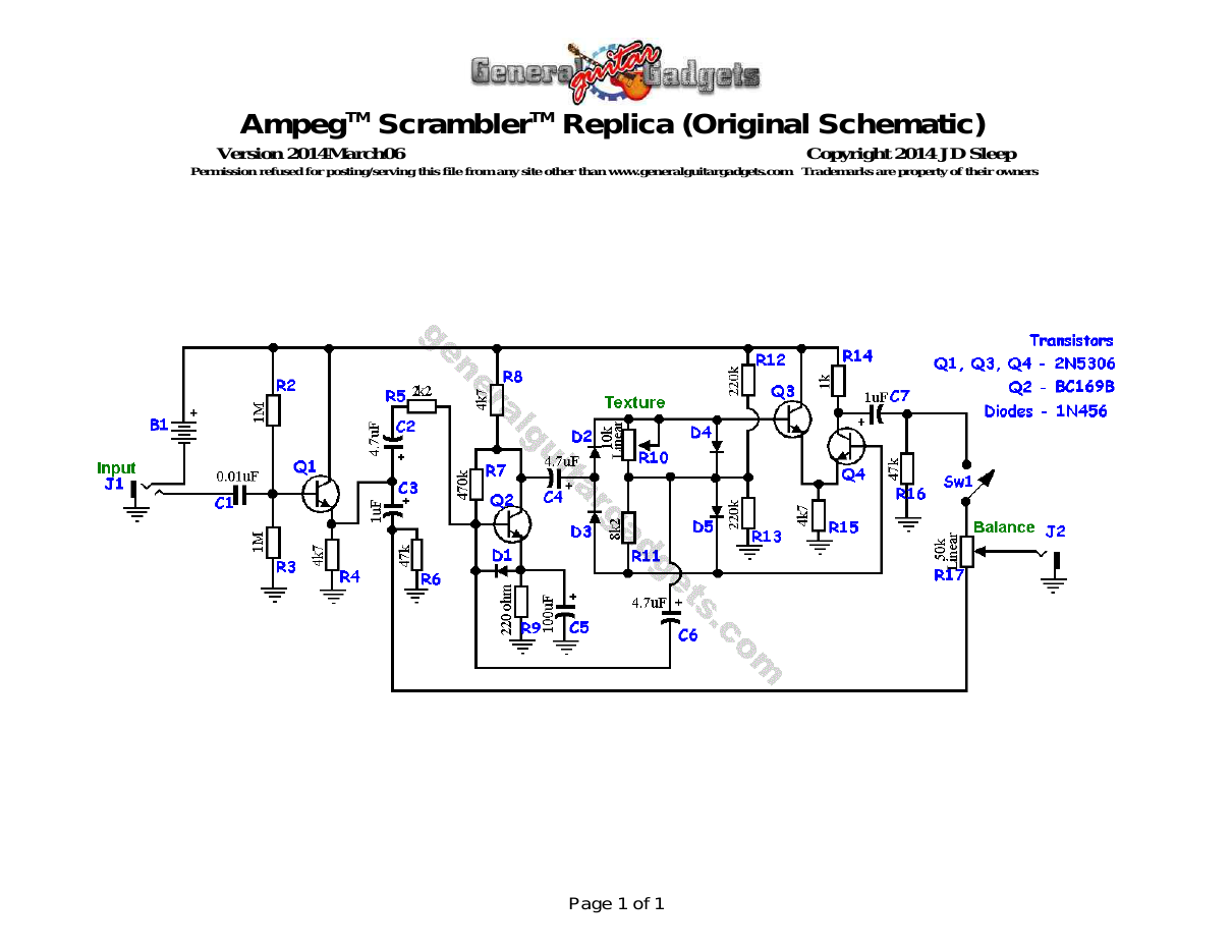
Schematic
Schematic
Parts layout
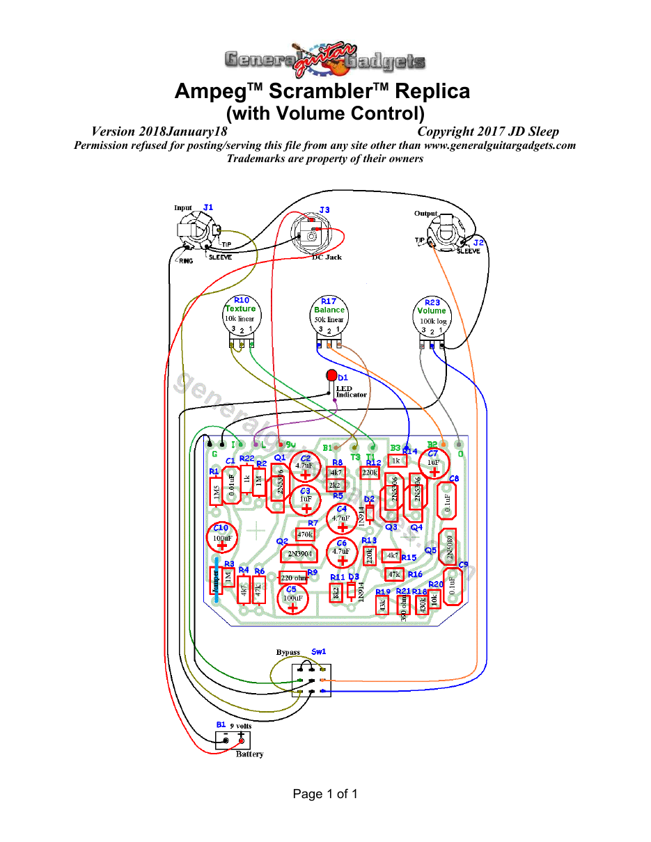
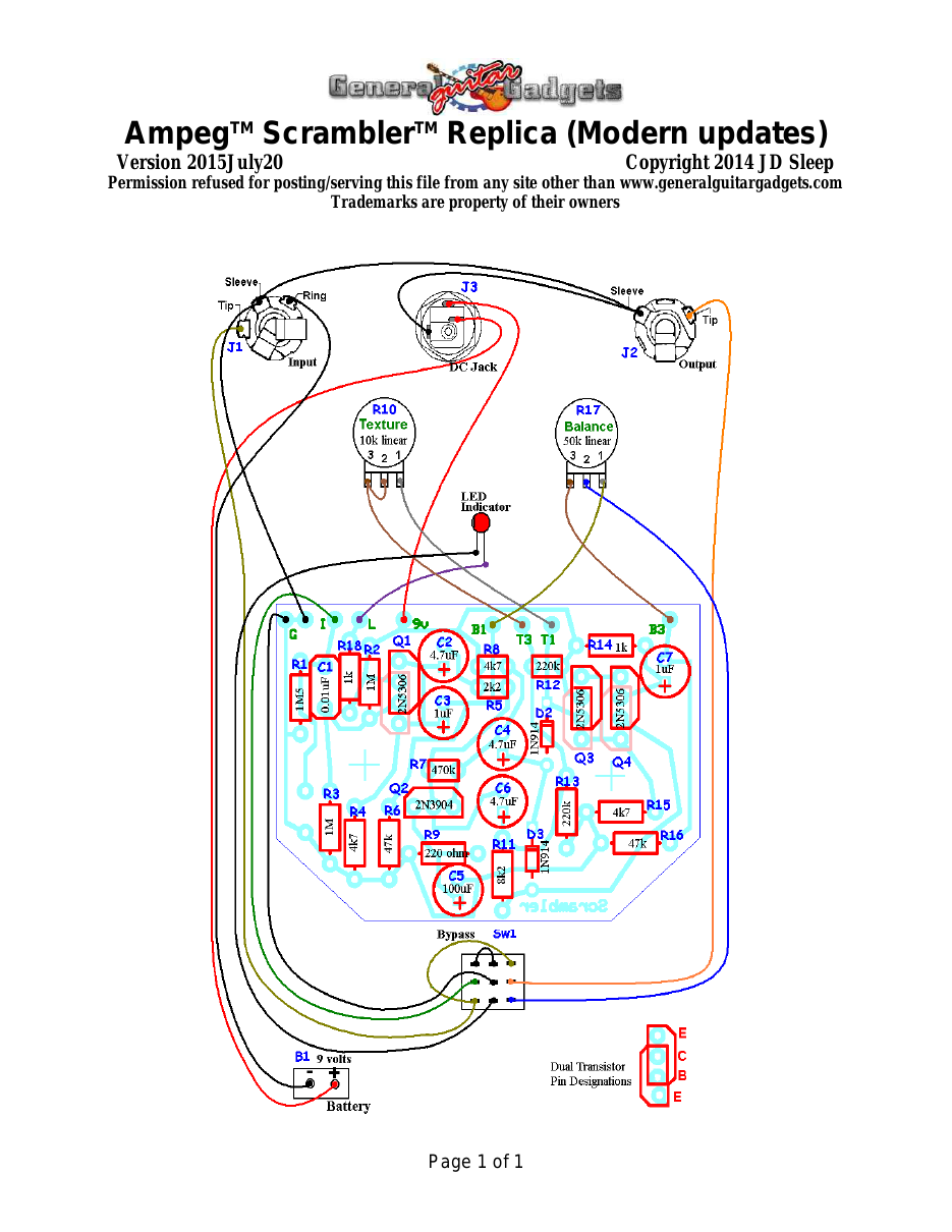
Parts Layout / Wiring Diagram
What you will need
Bill of Materials
Version 2017November06 · Copyright 2017 JD Sleep · Permission refused for posting/serving this file from any site other than www.generalguitargadgets.com · Trademarks are property of their owners
Resistors
| Resistor ID | Value | 3-band Marking | 4-band Marking |
|---|---|---|---|
| R1 | 1M5 (1.5M) | brown-green-green | brown-green-black-yellow |
| R2 | 1M | brown-black-green | brown-black-black-yellow |
| R3 | 1M | brown-black-green | brown-black-black-yellow |
| R4 | 4k7 (4.7k) | yellow-violet-red | yellow-violet-black-brown |
| R5 | 2k2 (2.2k) | red-red-red | red-red-black-brown |
| R6 | 47k | yellow-violet-orange | yellow-violet-black-red |
| R7 | 470k | yellow-violet-yellow | yellow-violet-black-orange |
| R8 | 4k7 (4.7k) | yellow-violet-red | yellow-violet-black-brown |
| R9 | 220 ohm | red-red-brown | red-red-black-black |
| R10 (Texture Control) | 10k Linear Potentiometer | ||
| R11 | 8k2 (8.2k) | gray-red-red | gray-red-black-brown |
| R12 | 220k | red-red-yellow | red-red-black-orange |
| R13 | 220k | red-red-yellow | red-red-black-orange |
| R14 | 1k | brown-black-red | brown-black-black-brown |
| R15 | 4k7 (4.7k) | yellow-violet-red | yellow-violet-black-brown |
| R16 | 47k | yellow-violet-orange | yellow-violet-black-red |
| R17 (Balance Control) | 50k Linear Potentiometer | ||
| R18 | 430k | yellow-orange-yellow | yellow-orange-black-orange |
| R19 | 43k | yellow-orange-orange | yellow-orange-black-red |
| R20 | 10k | brown-black-orange | brown-black-black-red |
| R21 | 390 ohm | orange-white-brown | orange-white-black-black |
| R22 | 1k | brown-black-red | brown-black-black-brown |
| R23 Volume Control) | 100k Log Potentiometer |
Capacitors
| Capacitor ID | Value | Type | Possible Marking |
|---|---|---|---|
| C1 | 0.01µF | Film | 103 |
| C2 | 4.7µF | Aluminum Electrolytic | 4.7µF |
| C3 | 1F | Aluminum Electrolytic | 1µF |
| C4 | 4.7µF | Aluminum Electrolytic | 4.7µF |
| C5 | 100µF | Aluminum Electrolytic | 100µF |
| C6 | 4.7µF | Aluminum Electrolytic | 4.7µF |
| C7 | 1µF | Aluminum Electrolytic | 1µF |
| C8 | 0.1µF | Film | 104 or “µ1” in the numbers |
| C9 | 0.1µF | Film | 104 or “µ1” in the numbers |
| C10 | 100µF | Aluminum Electrolytic | 100µF |
Potentiometers
| Part ID | Value | Type |
|---|---|---|
| R10 - Texture Control | 10k | Linear Taper |
| R17 – Balance Control | 50k | Linear Taper |
| R23 – Volume Control | 100k | Log (or Audio) Taper |
Other
| Part ID | Part Name |
|---|---|
| Q1 | 2N5306 |
| Q2 | 2N3904 (or other low gain NPN BJT) |
| Q3 | 2N5306 |
| Q4 | 2N5306 |
| Q5 | 2N5089 |
| D21, D3 | 1N914 |
| D1 | LED |
| J1 | Stereo quarter-inch jack |
| J2 | Mono quarter-inch jack |
| J3 | DC Jack |
| B1 | 9 volt battery (not included in the Kit) |
| Sw1 | Heavy Duty 3PDT footswitch 9v battery snap, Printed Circuit Board, 24 gauge stranded wire, Enclosure, Knobs |
How to build it
Instructions
Scrabbler With Volume Control Instructions
Version 2017November06 · Copyright 2017 JD Sleep · Permission refused for posting/serving this file from any site other than www.generalguitargadgets.com · Trademarks are property of their owners
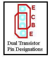
This is the Ampeg™ Scrambler™ Replica kit. This is a Fuzz/Octave unit. The Octave up sound is not as pronounced as some of the other Octave up stompboxes, but this one has a unique one-of-a-kind sound that you don't want to miss out on. This version has a transparent discrete boost stage so that a very useful Volume Control could be added. The boost stage does not alter the original tone of this effect. Use the project documents provided, starting with the General Build Instructions. Note that the PCB allows for different pinouts for transistors Q1, Q3 and Q4. We use the original number Darlington 2N5306 transistors in our kits. Other Darlingtons will work, but may have a EBC pinout. Follow the part placement/wiring diagram for correct placement of the 2N5306 transistors and be careful to insert those transistors in the correct 3 (of 4) holes.
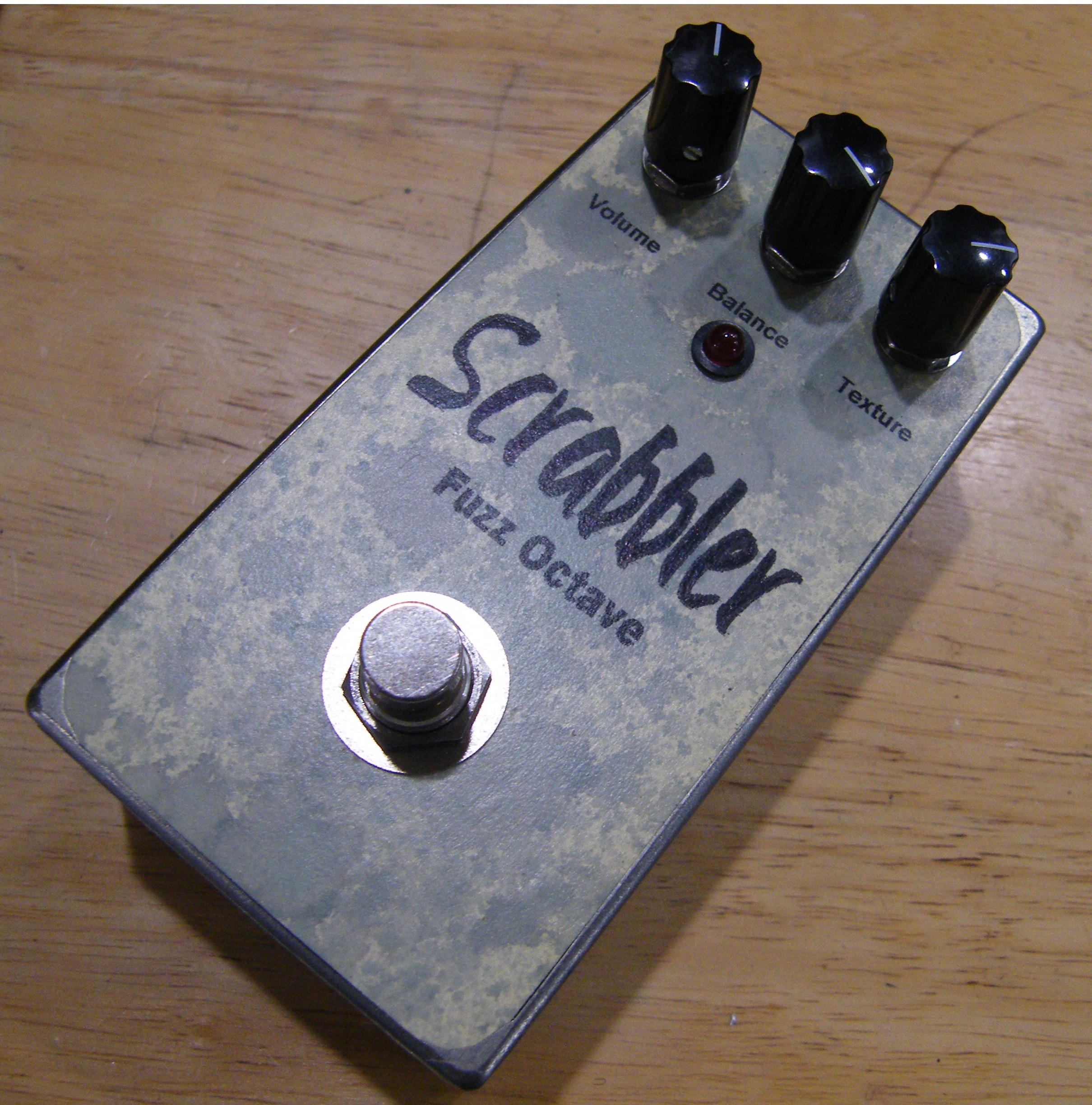
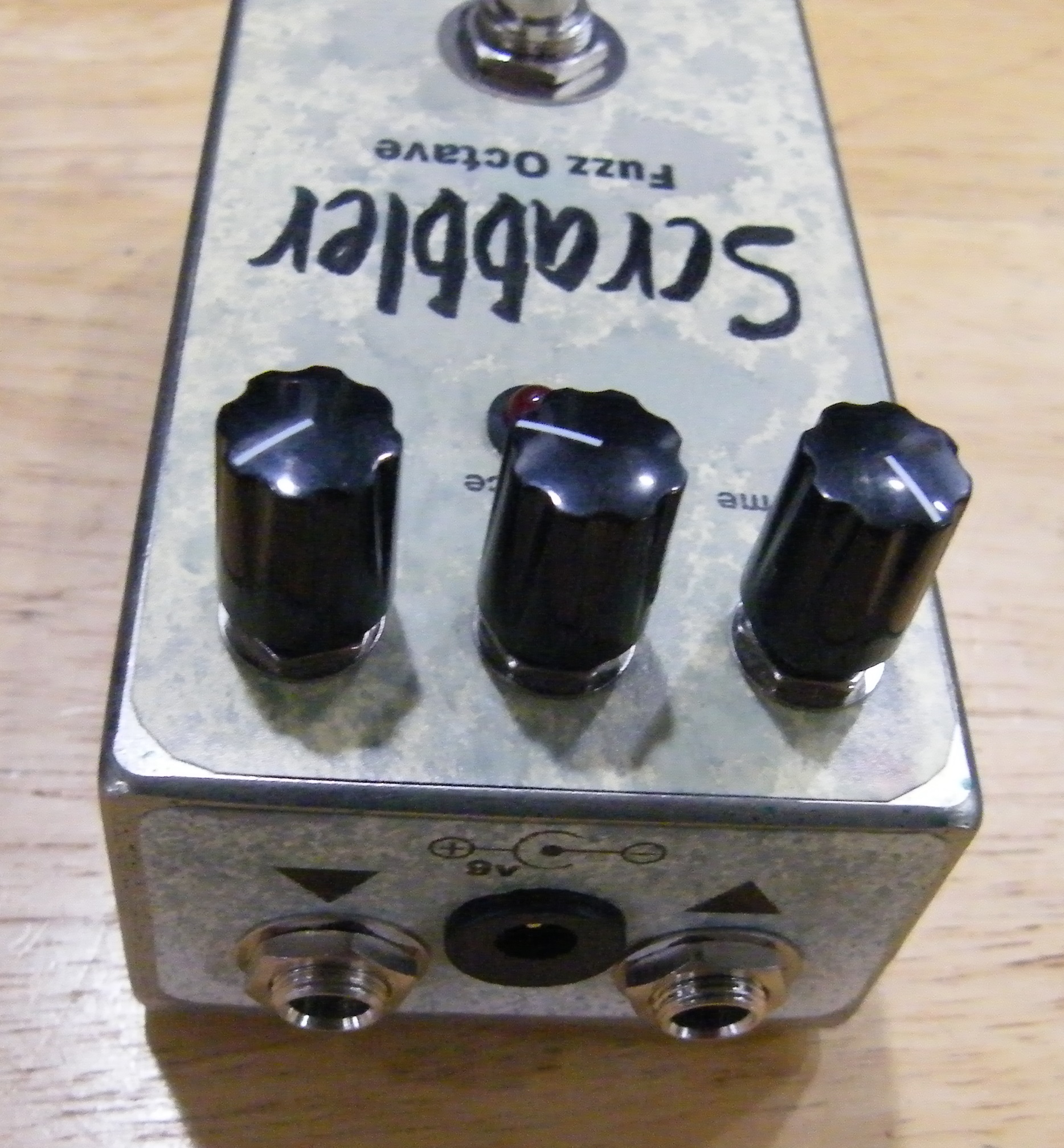
Note that all the capacitors, Except C1, C8 and C9 are polarized and need to be installed with the correct polarity. The long lead of the capacitors go in the square holes. Our kit has 1N914 for the diodes and a 2N3904 for Q2. These are not the original component types. Some folks make a case that you need the original components. We have compared our kit unit with a unit built with the original Q2 and Diode values. We can hear no difference at all. Here's an inside view of the unit we built to give you a real view of our construction.
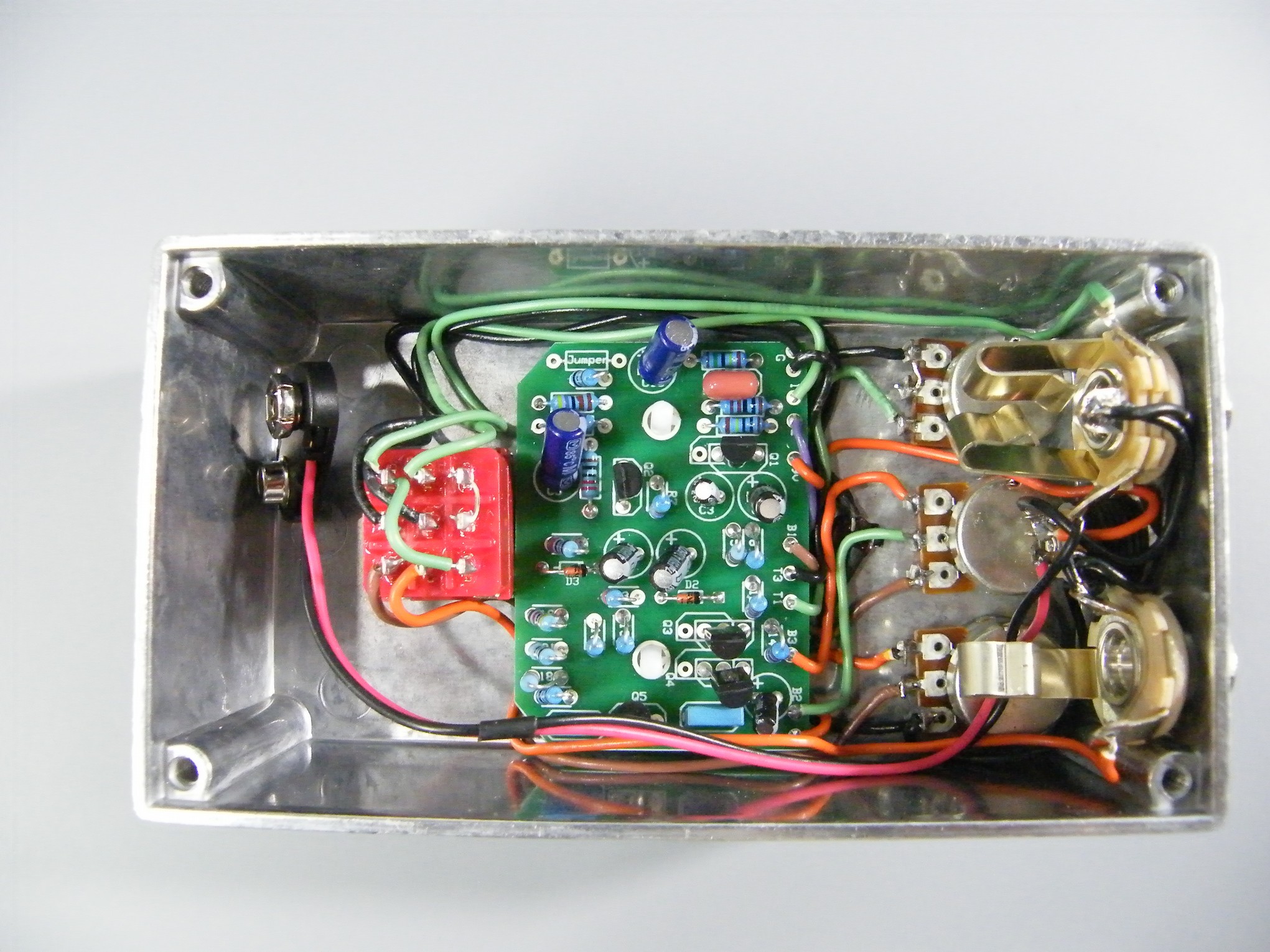
Here is a chart of voltages taken at the transistor pins. Use these voltages as a guideline. You may not get the exact readings listed, but should be somewhere in this general range.
Component
Location
9 volt power supply Q1
Q2
Q3
Q4
Q5
Voltage
9.5v
Collector
9.5v
Base
4.5v
Emitter
3.6v
Collector
4.5v
Base
0.9v
Emitter
0.2v
Collector
9.5v
Base
4.7v
Emitter
3.7v
Collector
9.2v
Base
4.7v
Emitter
3.7v
Collector
3.8v
Base
0.8v
Emitter
0.2v
Scrabbler Instructions
Version 2015July20 · Copyright 2014 JD Sleep · Permission refused for posting/serving this file from any site other than www.generalguitargadgets.com · Trademarks are property of their owners
This is the Ampeg™ Scrambler™ Replica kit. This is a Fuzz/Octave unit. The Octave up sound is not as pronounced as some of the other Octave up stompboxes, but this one has a unique one-of-a-kind sound that you don't want to miss out on. Use the project documents provided, starting with the General Build Instructions. Note that the PCB allows for different pinouts for transistors Q1, Q3 and Q4. We use the original number Darlington 2N5306 transistors in our kits. Other Darlingtons will work, but may have a EBC pinout. Follow the part placement/wiring diagram for correct placement of the 2N5306 transistors and be careful to insert those transistors in the correct 3 (of 4) holes.
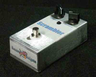
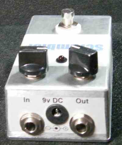
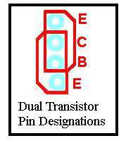
Note that all the capacitors, Except C1 are polarized and need to be installed with the correct polarity. The long lead of the capacitors go in the square holes. Our kit has 1N914 for the diodes and a 2N3904 for Q2. These are not the original component types. Some folks make a case that you need the original components. We have compared our kit unit with a unit built with the original Q2 and Diode values. We can hear no difference at all. Volume output on this unit is slightly above unity gain and it sounds great. Here's an inside view of the unit we built to give you a real view of our construction.
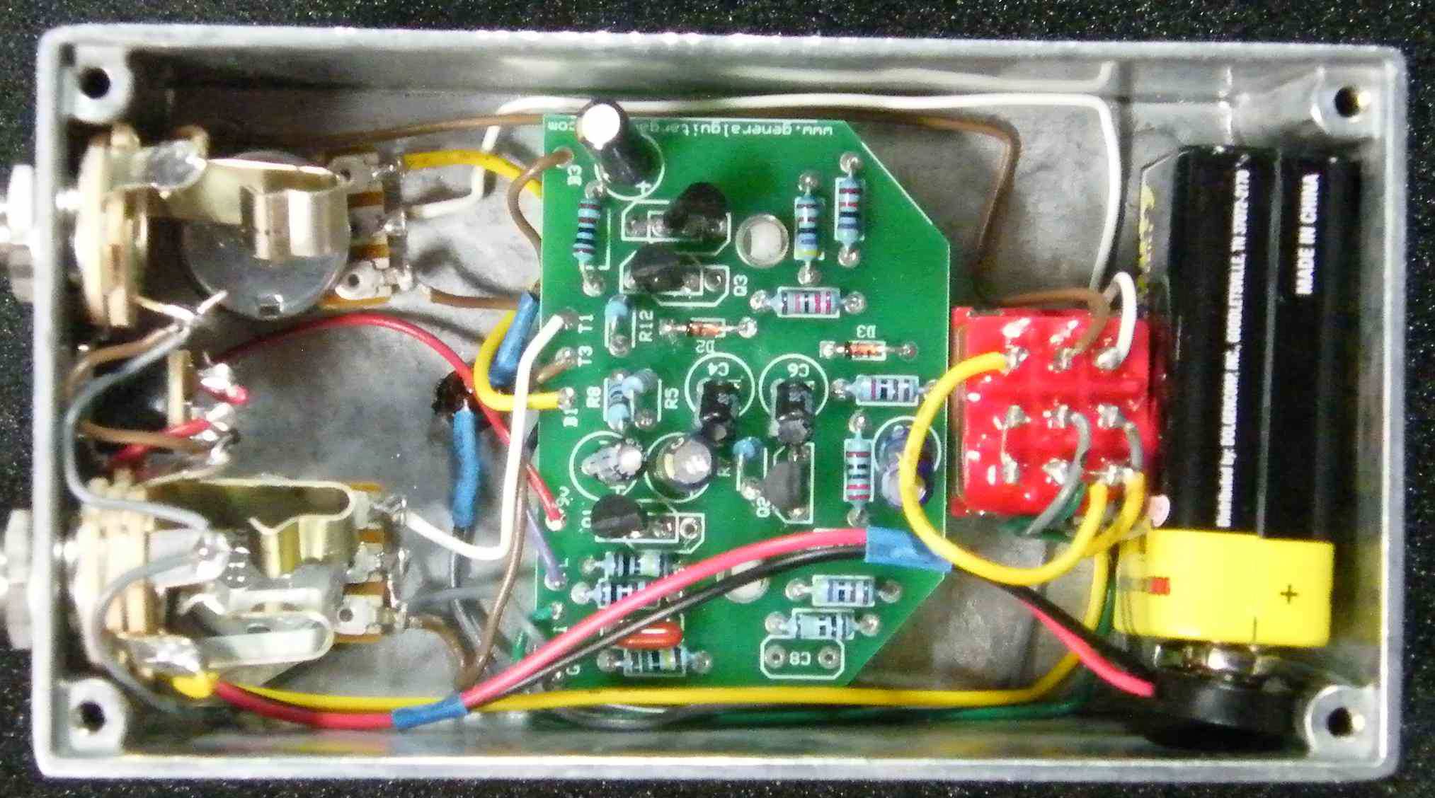
Here is a chart of voltages taken at the transistor pins. Use these voltages as a guideline. You may not get the exact readings listed, but should be somewhere in this general range.
Component
Location
9 volt power supply Q1
Q2
Q3
Q4
Voltage
9.5v
Collector
9.5v
Base
4.5v
Emitter
3.6v
Collector
4.5v
Base
0.9v
Emitter
0.2v
Collector
9.5v
Base
4.7v
Emitter
3.7v
Collector
9.2v
Base
4.7v
Emitter
3.7v
More about this project
Notes, sounds and related links
Updated Circuit With Volume Control
Original Circuit
Other Reference Files

Ready to build? We have the kit.
Buy an Ampeg™ Scrambler™ Complete Kit. Includes all the parts and materials you need to build one, all for about the price you would pay for a PCB and parts.

Would you like a Ready to Solder Circuit Board for this project? Note: If you buy the kit, the Ready-to-Solder Printed Circuit Board (RTS PCB) is included in the kit. You do not need to purchase this Ready to Solder Circuit Printed Board if you buy the kit.