
Project · Modulation/Echo
Weslie Modulator
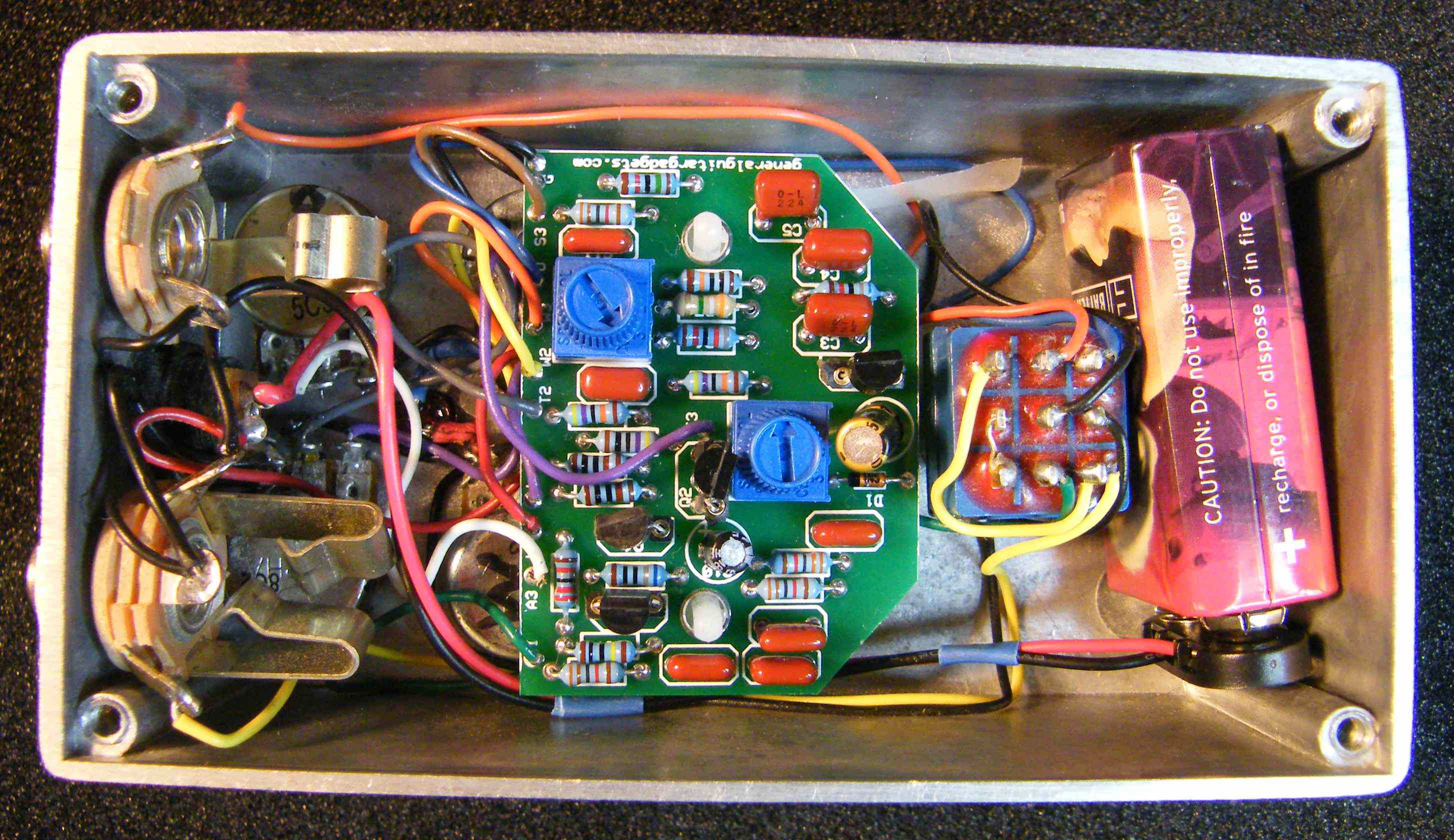
Here's the 'Leslie Effect Simulator' from March 1971 Popular Electronics. Contributed by Dean Hazelwanter. 1971 was a long time before the advent of the modern Leslie Simulators e.g. Hughes and Kettner Rotosphere, etc. This circuit is nowhere near the type of simulator available on today's commercial stompbox market. But it is a unique and interesting modulation device. We named it "Weslie" Since it's not really much like a Leslie, but it does have some wah and warbling.
Project files
Everything you need to build it
Weslie Modulator PCB file - For use only if you are a complete DIY person who wants to etch and drill your own PCB. Otherwise, we recommend you ignore this PCB mask and buy the Ready-to-Solder Printed Circuit Board or Complete Kit.
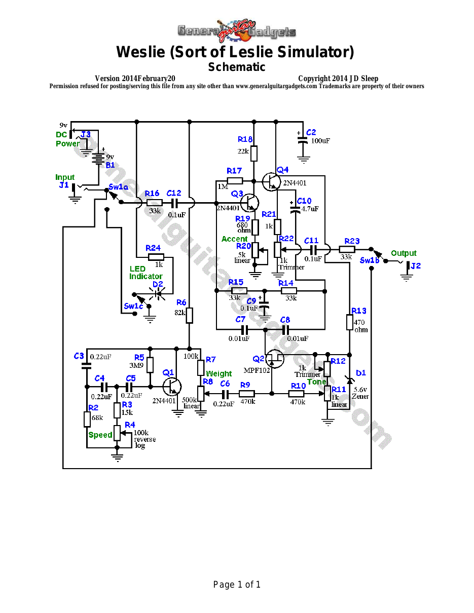
What you will need
Bill of Materials
Version 2015June10 · Copyright 2014 JD Sleep · Permission refused for posting/serving this file from any site other than www.generalguitargadgets.com · Trademarks are property of their owners
Resistors
| Resistor ID | Value | 3-band Marking | 4-band Marking |
|---|---|---|---|
| R1 | none | ||
| R2 | 68k | blue-gray-orange | blue-gray-black-red |
| R3 | 15k | brown-green-orange | brown-green-black-red |
| R4 (Speed Control Potentiometer) | 100k Reverse Log | ||
| R5 | 3M9 (3.9M) | orange-white-green | orange-white-black-yellow |
| R6 | 82k | gray-red-orange | gray-red-black-red |
| R7 | 100k | brown-black-yellow | brown-black-black-orange |
| R6 (Weight Control Potentiometer) | 500k Linear | ||
| R9 | 470k | yellow-violet-yellow | yellow-violet-black-orange |
| R10 | 470k | yellow-violet-yellow | yellow-violet-black-orange |
| R11 (Tone Control Potentiometer) | 1k Linear | ||
| R12 | 1k Trimmer Potentiometer | ||
| R13 | 470 ohm | yellow-violet-brown | yellow-violet-black-black |
| R14 | 33k | orange-orange-orange | orange-orange-black-red |
| R15 | 33k | orange-orange-orange | orange-orange-black-red |
| R16 | 33k | orange-orange-orange | orange-orange-black-red |
| R17 | 1M | brown-black-green | brown-black-black-yellow |
| R18 | 22k | red-red-orange | red-red-black-red |
| R19 | 680 ohm | blue-gray-brown | blue-gray-black-black |
| R20 (Accent Control Potentiometer) | 5k Linear | ||
| R21 | 1k | brown-black-red | brown-black-black-brown |
| R22 | 1k Trimmer Potentiometer | ||
| R23 | 33k | orange-orange-orange | orange-orange-black-red |
| R24 | 1k | brown-black-red | brown-black-black-brown |
Capacitors
| Capacitor ID | Value | Type | Possible Marking |
|---|---|---|---|
| C1 | none | ||
| C2 | 100µF | Aluminum Electrolytic | 100µF |
| C3 | 0.22µF | Film or Ceramic | 224 |
| C4 | 0.22µF | Film or Ceramic | 224 |
| C5 | 0.22µF | Film or Ceramic | 224 |
| C6 | 0.22µF | Film or Ceramic | 224 |
| C7 | 0.01µF | Film or Ceramic | 103 |
| C8 | 0.01µF | Film or Ceramic | 103 |
| C9 | 0.1µF | Film or Ceramic | 104 |
| C10 | 4.7µF | Aluminum Electrolytic | 4,7µF |
| C11 | 0.1µF | Film or Ceramic | 104 |
| C12 | 0.1µF | Film or Ceramic | 104 |
Potentiometers
| Part ID | Value | Type |
|---|---|---|
| R4 - Speed Control | 100k | Reverse Log Taper |
| R8 - Weight Control | 500k | Linear Taper |
| R11 - Tone Control | 1k | Linear Taper |
| R20 - Accent Control | 5k | Linear Taper |
Other
| Part ID | Part Name |
|---|---|
| D1 | 1N5232B (5.6v Zener) |
| D2 | LED |
| Q1 | 2N4401 bipolar junction transistor (or similar) |
| Q2 | MPF102 JFET transistor |
| Q3 | 2N4401 bipolar junction transistor (or similar) |
| Q4 | 2N4401 bipolar junction transistor (or similar) |
| J1 | Stereo quarter-inch jack |
| J2 | Mono quarter-inch jack |
| J3 | DC Jack |
| B1 | 9 volt battery (not included in the Kit) |
| Sw1 | Heavy Duty 3PDT foot switch 9v battery snap, Printed Circuit Board, 24 gauge stranded wire, Enclosure, Knobs |
How to build it
Instructions
Version 2015November17 · Copyright 2013 JD Sleep · Permission refused for posting/serving this file from any site other than www.generalguitargadgets.com · Trademarks are property of their owners
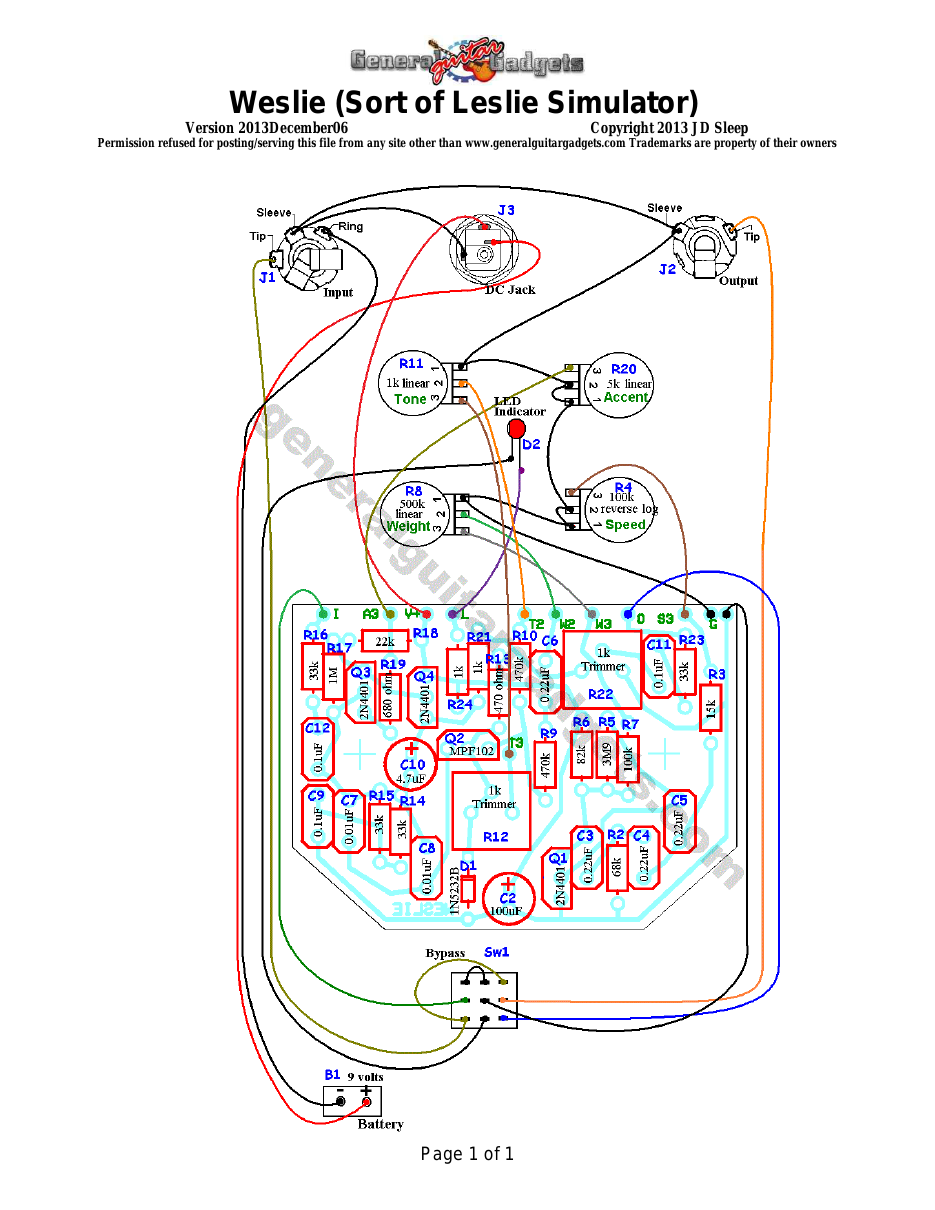
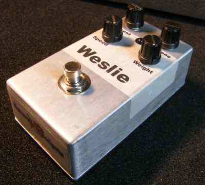
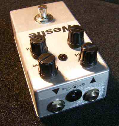
This is a so-called Leslie Simulator from 1971. It doesn't sound much like a Leslie to us, so we altered the name to “Weslie” since it has some very nice warble and wah type modulations sounds on some settings. It does have somewhat of a Leslie sound on some settings and with the right tones going into the unit (it was, of course, designed for an organ input). Follow the General Instructions and the Part Placement/Wiring Diagram. Look at the original article for instructions on how to use it and how to set the trimmers and controls. We used 2N4401 or 2N5089 transistors for Q1, Q3 and Q4. Q2 is MPF102. D1 (the Zener) is 1N5232B.
Have fun, comments and questions are welcome and can be sent to [email protected] Here is a chart of voltages taken at the transistor pins. This information can be used to help you find and fix problems if your Weslie doesn't work when you test it. Component
Location
9 volt supply Q1
Q2
Voltage
9.2v
Collector
1.6v (varies with speed)
Base
0.6v
Emitter
0v
Drain
4.8v
Source
0.01v
Component
Q3
Q4
Location
Voltage
Gate
2.0v (varies with speed)
Collector
3.5v
Base
1.8v
Emitter
1.3v
Collector
9.2v
Base
3.5v
Emitter
2.9v
More about this project
Notes, sounds and related links


Ready to build? We have the kit.
Buy a Weslie Modulator Complete Kit. Includes all the parts and materials you need to build one, all for about the price you would pay for a PCB and parts.
Would you like a Ready to Solder Circuit Board for this project?