
Project files
Everything you need to build it
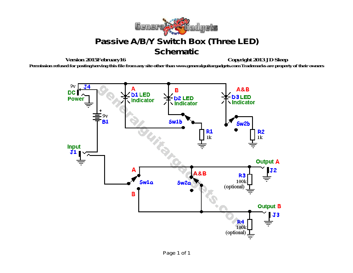
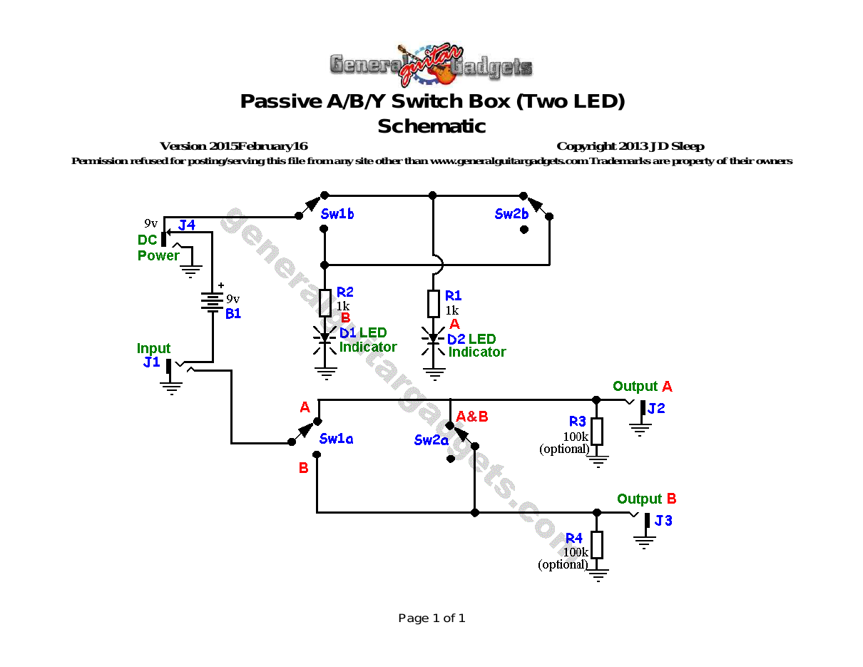
Schematic
Schematic
Parts layout
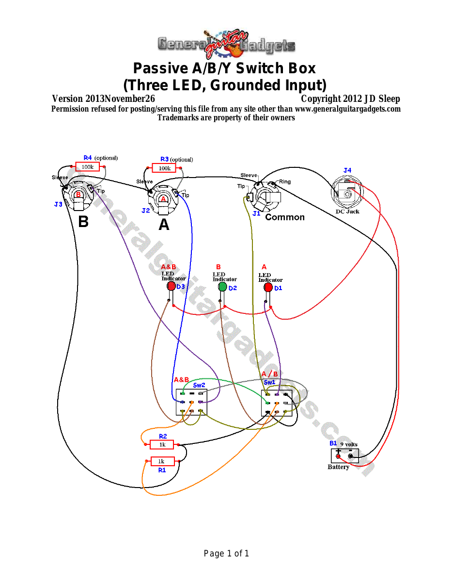
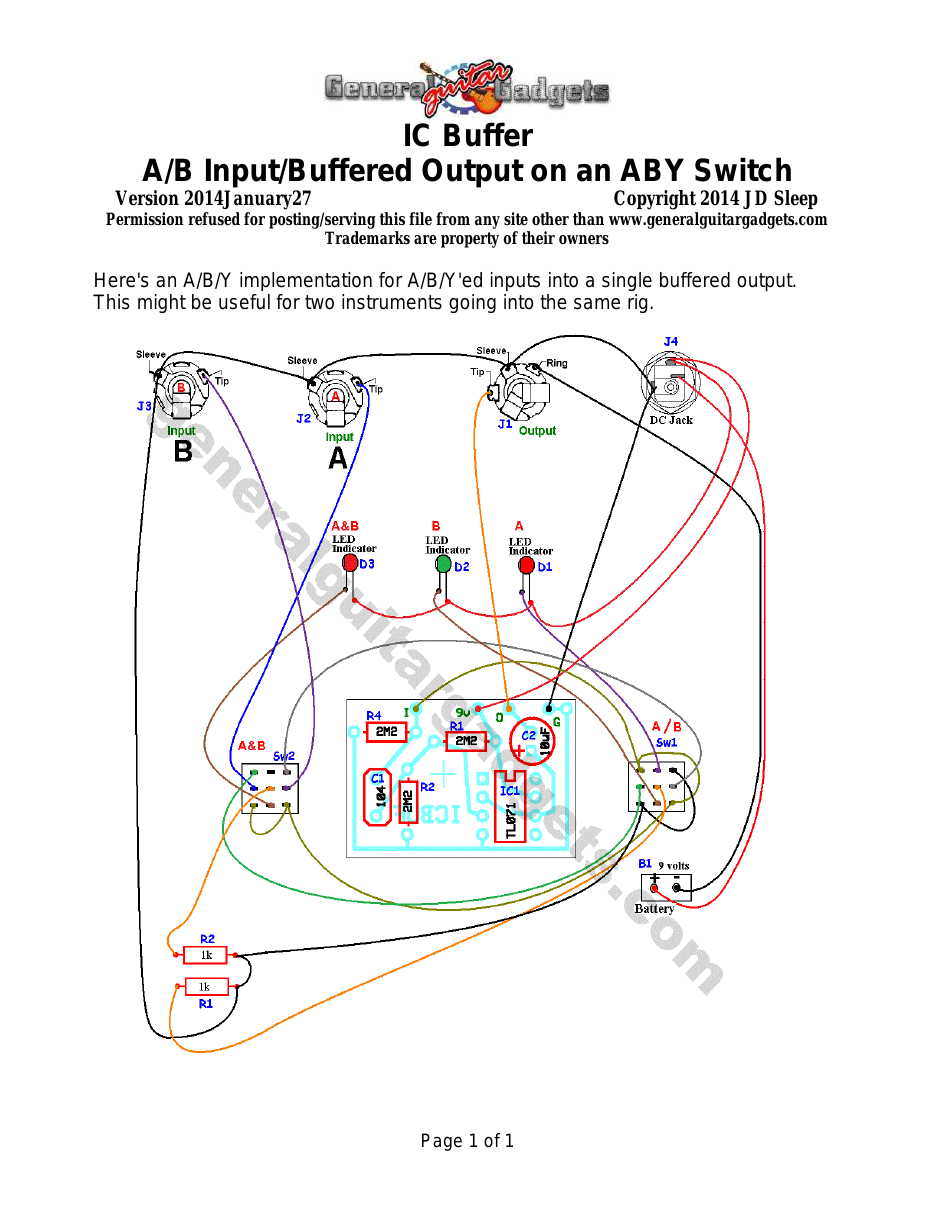
Parts Layout / Wiring Diagram
What you will need
Bill of Materials
Version 2013November17 · Copyright 2013 JD Sleep · Permission refused for posting/serving this file from any site other than www.generalguitargadgets.com · Trademarks are property of their owners
Resistors
| Resistor ID | Value | 3-band Marking | 4-band Marking |
|---|---|---|---|
| R1 | 1k | brown-black-red | brown-black-black-brown |
| R2 | 1k | brown-black-red | brown-black-black-brown |
| R3 (optional) | 100k | brown-black-yellow | brown-black-black-orange |
| R4 (optional) | 100k | brown-black-yellow | brown-black-black-orange |
Other
| Part ID | Part Name |
|---|---|
| D1 | “A” Status indicator Red LED |
| D2 | “B” Status indicator Green LED |
| D3 | A&B Status indicator Red LED |
| J1 | Stereo quarter-inch jack (Input) |
| J2 | Mono quarter-inch jack (Output A) |
| J3 | Mono quarter-inch jack (Output B) |
| J4 | DC Jack |
| B1 | 9 volt battery (not included in the Kit) |
| Sw1 | Heavy Duty 3PDT foot switch |
| Sw2 | Heavy Duty 3PDT foot switch 9v battery snap, 3 LED mounting clips 24 gauge stranded wire, Enclosure |
How to build it
Instructions
Version 2013November28 · Copyright 2013 JD Sleep · Permission refused for posting/serving this file from any site other than www.generalguitargadgets.com · Trademarks are property of their owners
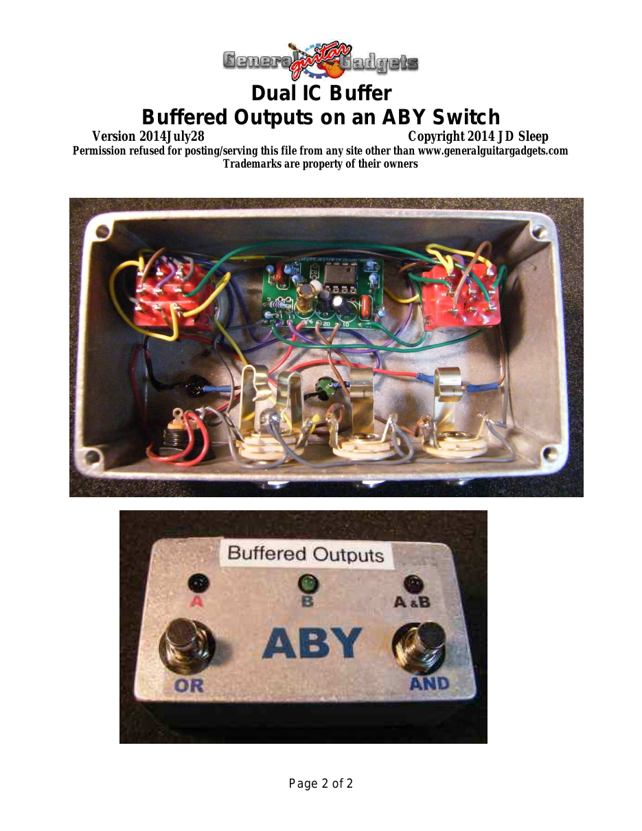
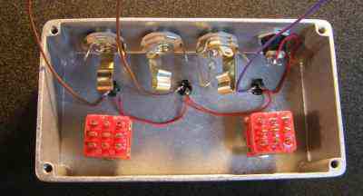
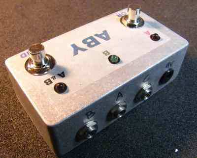
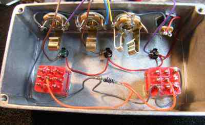
This is the A/B/Y Switch Box kit. Simply a passive switch box to switch one input to two outputs or two inputs to one output. It has an addition switch to switch on both A and B at the same time. It is called passive, since the signal paths do not have any active circuits (no boost or buffering, etc). The 9 volt power going into the box is only to control the LED indicators. Use the project documents provided, be sure to read through the General Build Instructions, even though there is no circuit board on this project. Just wire the jacks, switch, resistor and LEDs according to the wiring diagram. 1 - Mount all the parts into the enclosure as shown in the photos above. 2 - Solder tack all the wiring to the LED as shown below. To solder tack - strip the end of the wire, put some solder on it and put some solder on the trimmed down LED wire and hold the two together and touch it with the soldering iron. Hold it still till it cools.
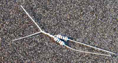
3 – Solder the wires to the jacks. On the extra ground wire solder tack the two 1k resistors to the end. Start by twisting the two 1k resisters together on one end. Trim the extra off the twisted end and then solder tack the wire to both
4 – Solder tack the other ends of the resistors to wires and wire and solder them to the switches according to the wiring diagram.
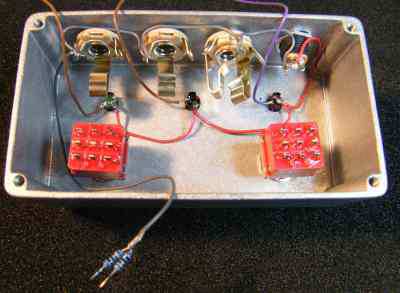
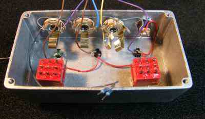
5 – Finish the rest of the wiring according to the wiring diagram.
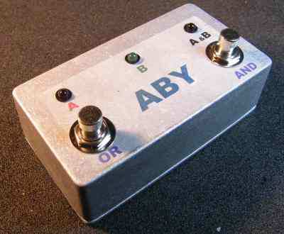
The photo shows the kit completed. Insulating the bare solder joints can be a bit tricky. We used heat-shink tubing on some of them, but there are several connections with three wires, so tubing won't work. We used Liquid Electrical Tape to insulate the LED resistors and connections and also the 3-way LED connections. If you internet search “liquid electrical tape” you can find several sources and it is
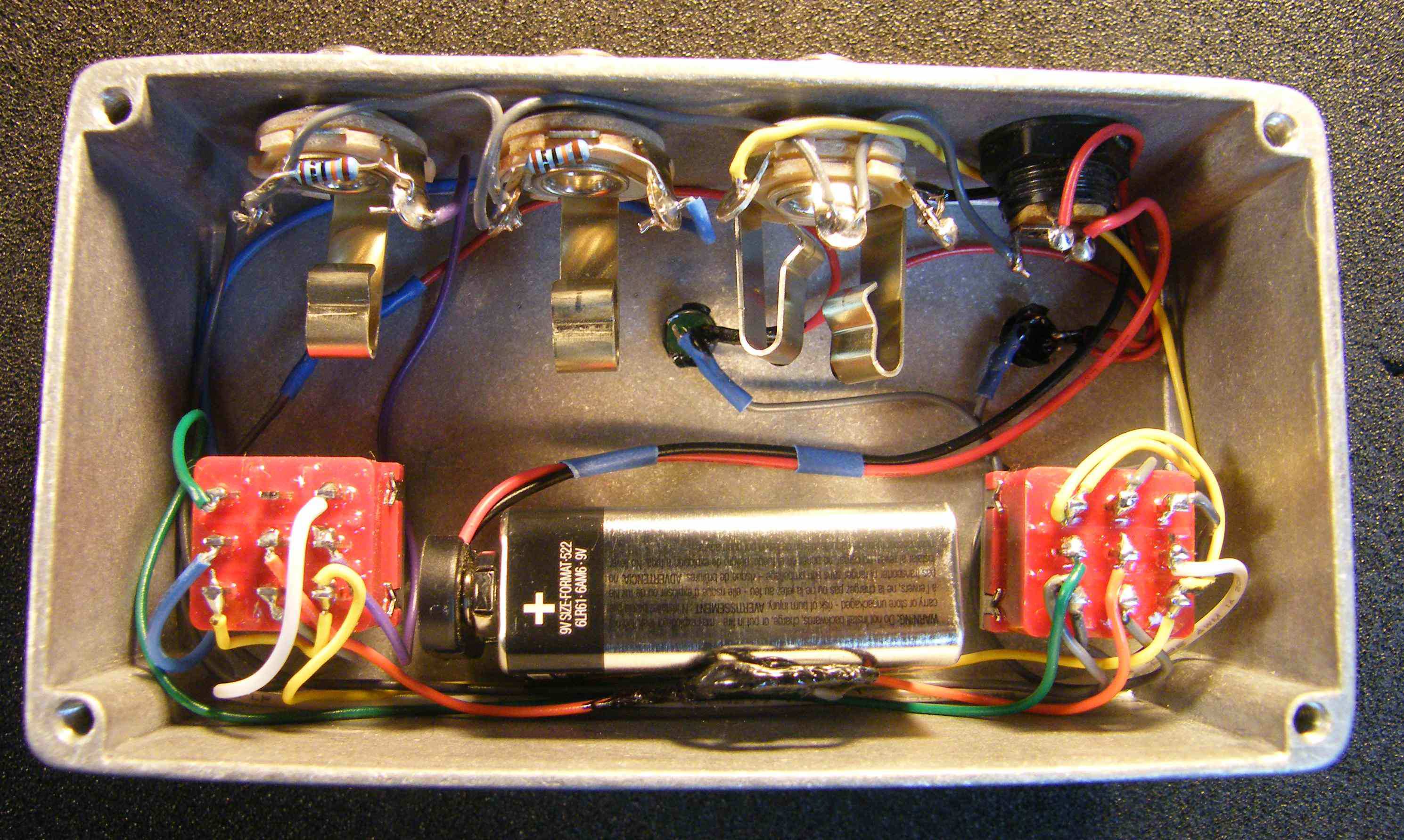
GREAT STUFF to have around the work bench! That's it. Very simple project and it can be a very useful tool. This could easily be upgraded to an “active” ABY switcher by adding a couple of IC Buffers on the A and B outputs.
More about this project
Notes, sounds and related links
Passive A/B/Y Instructions
This is a Passive A/B/Y switch box with input grounding (for the input not in use). There are some examples of how to use this box below. The circuit is passive except for the LED indicators to indicate which "channel" is active. The two channels are interchangeable as input or output channels as illustrated in the examples below. This project is more complicated than some due to the input grounding. There are some simpler version schematics in the section below these project files, in case you want to chose a simpler version.
Active A/B/Y Instructions
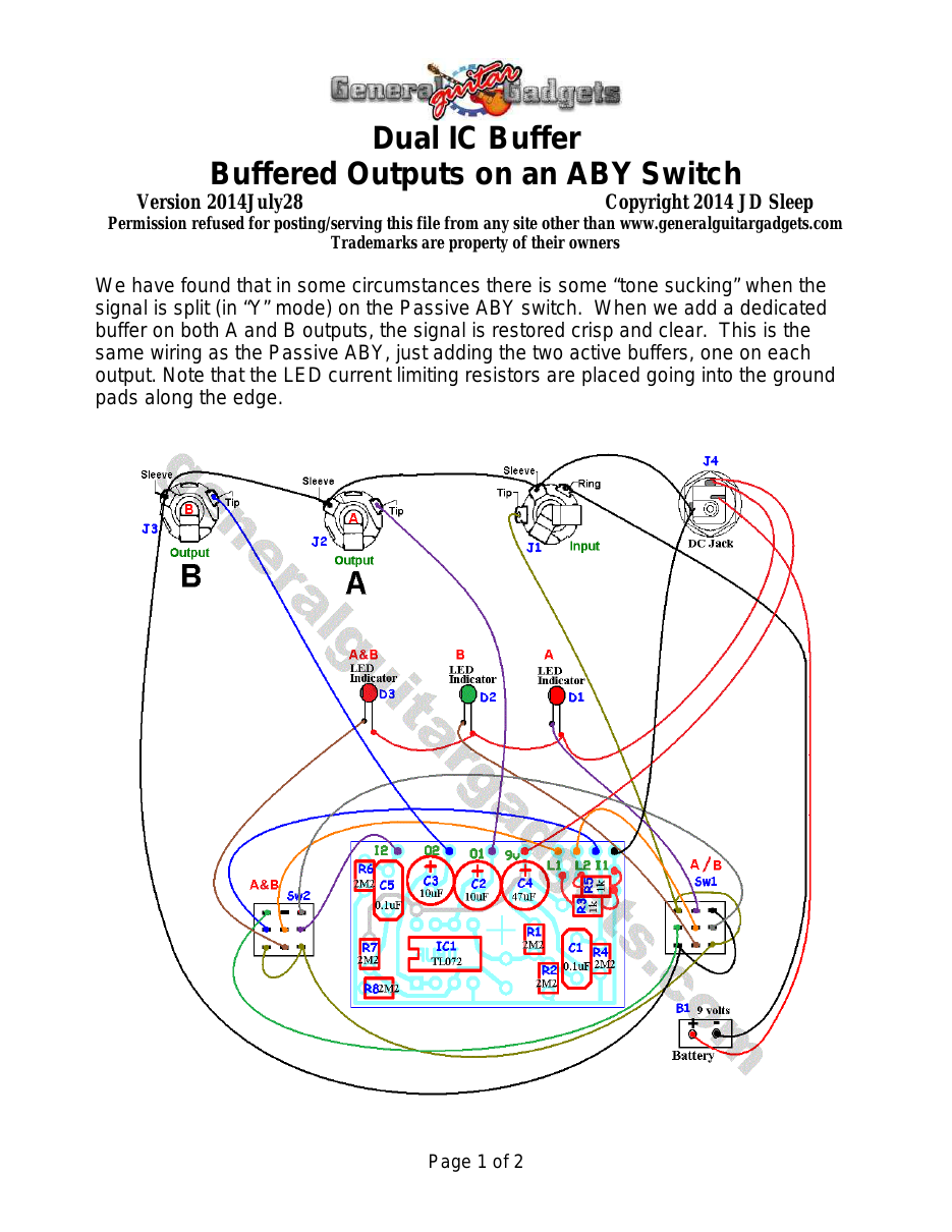
Here are some Diagrams with Active Buffers in the A/B/Y switcher. Once you put active components in it, it can no longer be used "reversible". It either has A/B/Y inputs or A/B/Y outputs, but not both. So here is a buffered version of each. These use either the ICBUF PCB or the Dual ICBUF PCB available from this site.
Other A/B/Y Schematics
Here are some other examples of ABY switch boxes. We chose the project above as being the best since it has grounding for the unused channel and a separate "A and B" LED indicator, so that when you come out of the "And" mode you will know which channel you will be on.
Buy An A/B/Y Kit
Ready to build? We have the kit.
Buy an A/B/Y Switch Box Complete Kit. Includes all the parts and materials you need to build one, all for about the price you would pay for the parts. 