
Project · Bass
Adamu Bass Preamp/Distortion
The Adamu is an awesome bass preamp and distortion by J. Michael Pedals. It is based on the DOD™ 250 ('77 Grey) Guitar Distortion, but tuned for bass.
If you're building on the PCB marked "DIST2" use these files:
Project files
Everything you need to build it
Schematic
Schematic
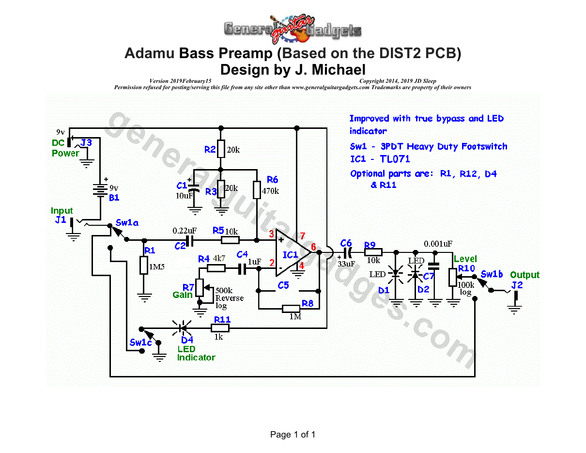
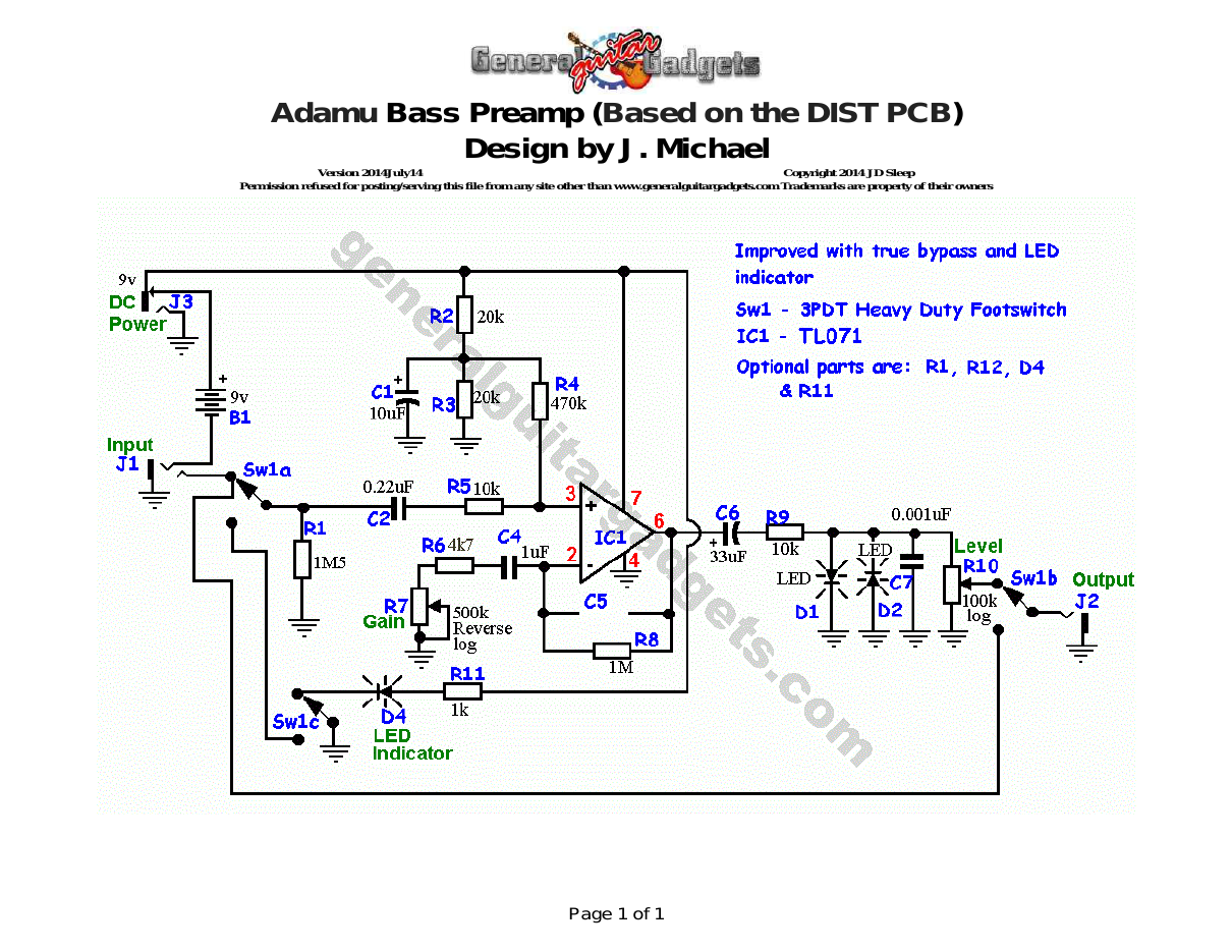
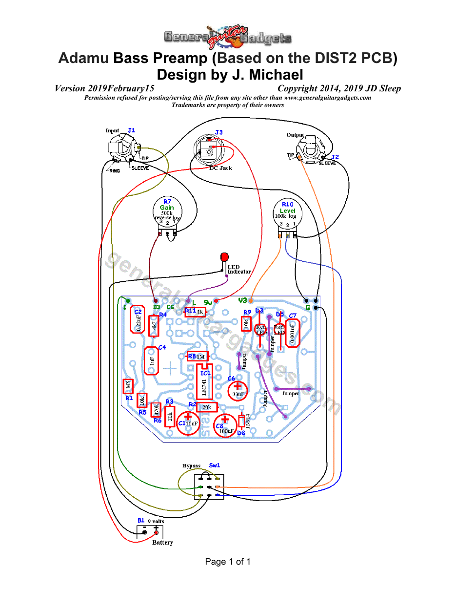
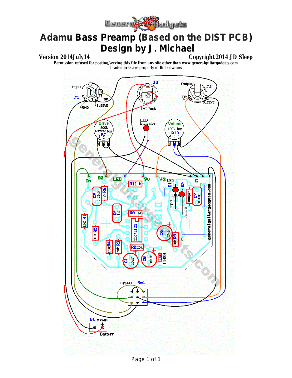
Parts layout
Parts Layout / Wiring Diagram
What you will need
Bill of Materials
Version 2019February25 · Copyright 2014 JD Sleep · Permission refused for posting/serving this file from any site other than www.generalguitargadgets.com · Trademarks are property of their owners
Resistors
| Resistor ID | Value | 3-band Marking | 4-band Marking |
|---|---|---|---|
| R1 | 1M5 | brown-green-green | brown-green-black-yellow |
| R2 | 20k | red-black-orange | red-black-black-red |
| R3 | 20k | red-black-orange | red-black-black-red |
| R4 | 4k7 (4.7k) | yellow-violet-red | yellow-violet-black-brown |
| R4 (optional value) | 47k (this is an optional value, see instructions for details) | yellow-violet-orange | yellow-violet-black-red |
| R5 | 10k | brown-black-orange | brown-black-black-red |
| R6 | 470k | yellow-violet-yellow | yellow-violet-black-orange |
| R7 | 500k Reverse Log Potentiometer | ||
| R8 | 1M | brown-black-green | brown-black-black-yellow |
| R9 | 10k | brown-black-orange | brown-black-black-red |
| R10 | 100k Log Potentiometer | ||
| R11 | 1k | brown-black-red | brown-black-black-brown |
| R12 (optional) | 100 ohm | brown-black-brown | brown-black-black-black |
Capacitors
| Capacitor ID | Value | Type | Possible Marking |
|---|---|---|---|
| C1 | 10µF | Tantalum or Aluminum Electrolytic | 10uF |
| C2 | 0.22µF | Film | 224 |
| C3 | none | ||
| C4 | 1µF | Film or Ceramic (non-polarized) | 105 or 1µF |
| C6 | 33µF | Aluminum Electrolytic or Tantalum | 33µF |
| C7 | 0.001µF | Film or Ceramic | 102 or 1n |
| C8 (optional) | 100µF | Aluminum Electrolytic | 100µF |
Potentiometers
| Part ID | Value | Type |
|---|---|---|
| R7 - Gain | 500k | Reverse Log Taper Potentiometer |
| R10 - Volume | 100k | Log (Audio) Taper Potentiometer |
Other
| Part ID | Part Name |
|---|---|
| IC1 | TL071 Opamp |
| D1 | Red LED |
| D2 | Red LED |
| D4 | Status Indicator LED and holder |
| D8 (optional) | 1N4001 or 1N914 |
| J1 | Stereo quarter-inch jack |
| J2 | Mono quarter-inch jack |
| J3 | DC Jack |
| B1 | 9 volt battery (not included in the Kit) |
| Sw1 | Heavy Duty 3PDT foot switch 9v battery snap, Printed Circuit Board 24 gauge stranded wire, Enclosure, Knobs |
How to build it
Instructions
Version 2014July28 · Copyright 2014 JD Sleep · Permission refused for posting/serving this file from any site other than www.generalguitargadgets.com · Trademarks are property of their owners
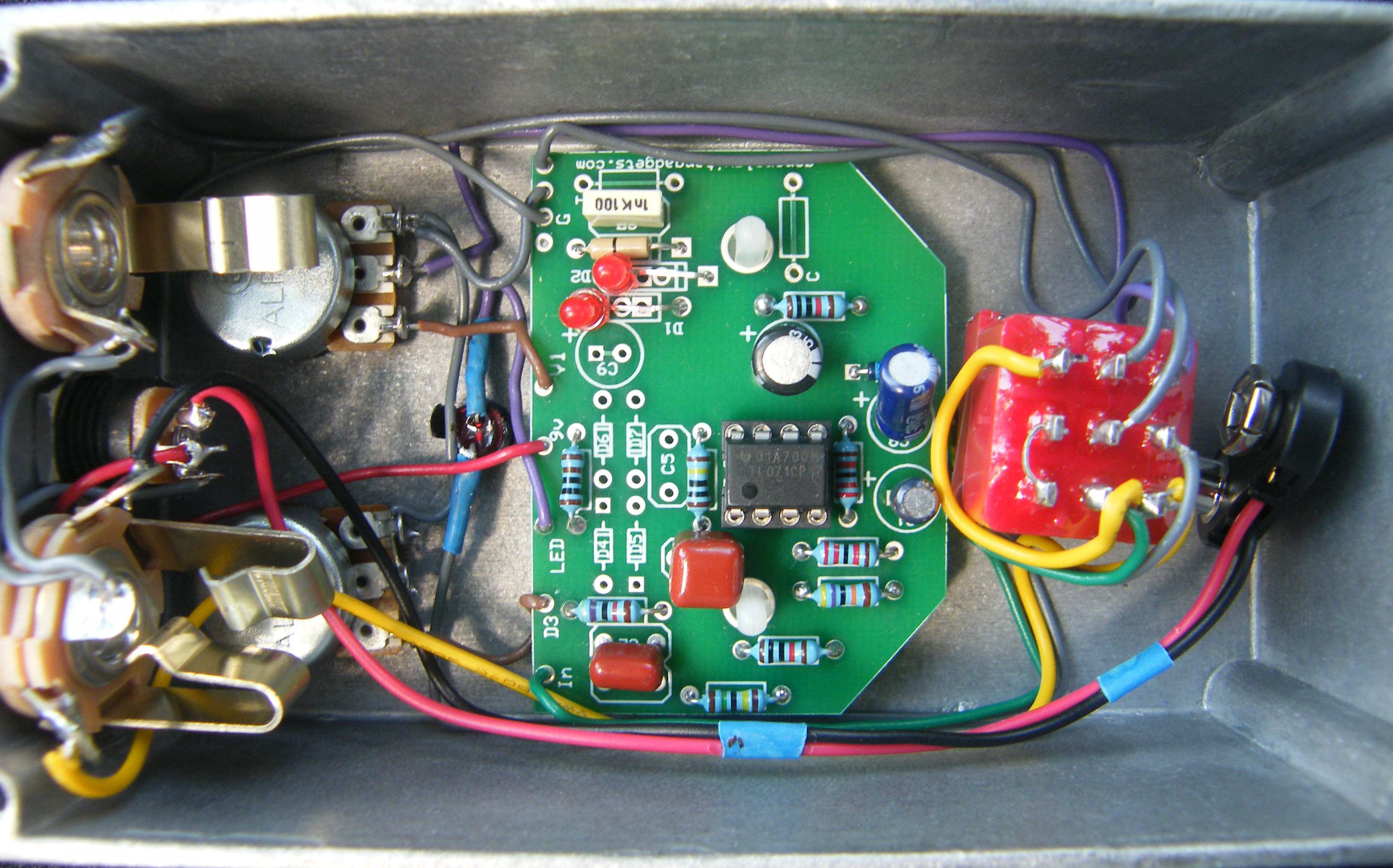
This is the Adamu Bass Preamp or Distortion. Use the project documents provided, starting with the General Build Instructions. Make sure the polarized capacitors are installed correctly according to the layout/wiring diagram. Note that there are several blank spaces for components since this is a “Multi-Use” PCB. That is okay, just follow the layout/wiring diagram and the photo below. There are three jumpers that are built in to the top layer of the PCB. They are sort of violet color on the layout/wiring diagrams. If you are using one of our PCB, you do not need to install jumpers there. Here's an inside view of the unit we built to give you some general ideas if needed.
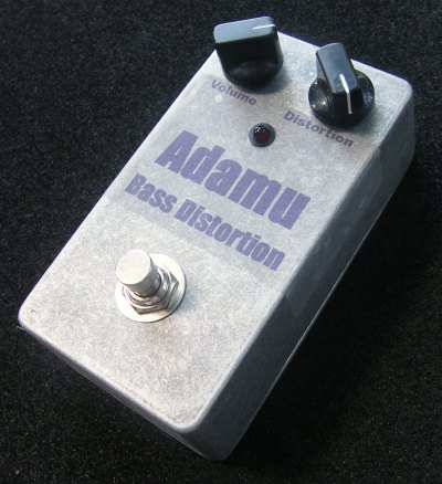
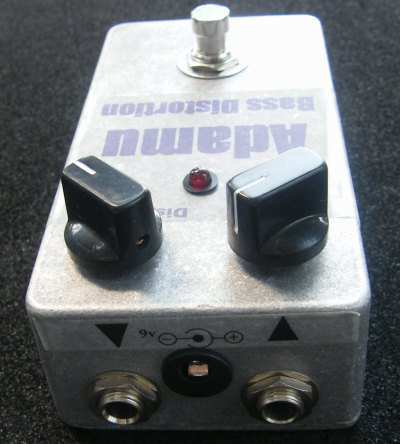
Comments and questions are welcome and can be sent to [email protected] Here is a chart of voltages taken at the transistor and IC pins. This information can be used to help find and fix problems if your Adamu doesn't work when you test it.
Component
Location
9 volt power supply IC1
Voltage
9.4v
Pin 1
0.1v
Pin 2
4.7v
Pin 3
4.5v
Pin 4
0v
Pin 5
0.1v
Pin 6
4.7v
Pin 7
9.4v
Pin 8
0.0v
More about this project
Notes, sounds and related links
If you're building on the PCB marked "DIST" use these files:
Use these files for either PCB build:
Adamu Sound Sample


Ready to build? We have the kit.
Buy an Adamu Complete Kit. Includes all the parts and materials you need to build one, all for about the price you would pay for a PCB and parts.
Would you like a Ready to Solder Circuit Board for this project? Note: If you buy the kit, the Ready-to-Solder Printed Circuit Board (RTS PCB) is included in the kit. You do not need to purchase this Ready to Solder Circuit Printed Board if you buy the kit.