
Project · Phase Shifters
MXR™ Phase 90™ (Script Logo)
This is the original MXR™ Phase 90™ Phase Shifter (script logo) Replica known as P90. This is a classic phase shifter. We chose to use this layout since the 741 ICs seem to be part of the "magic" sound of the old Script Logo version. The layout is very similar to the original MXR™ layout.
Project files
Everything you need to build it
P90 Ready-For-Transfer Printed Circuit Board Layout - For use only if you are a complete DIY person who wants to etch and drill your own PCB. Otherwise, we recommend you ignore this PCB mask and buy the Ready-to-Solder Printed Circuit Board or Complete Kit.
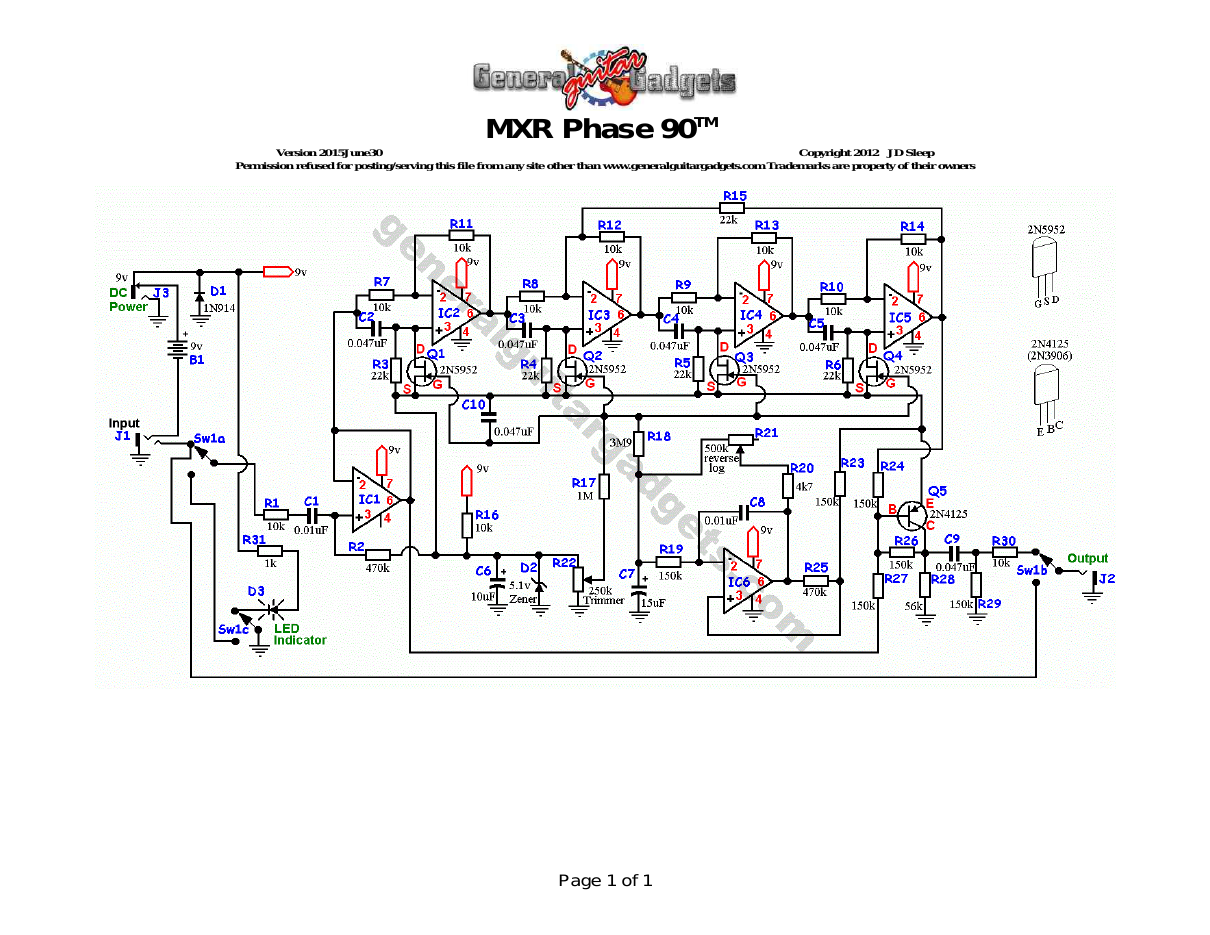
Parts layout
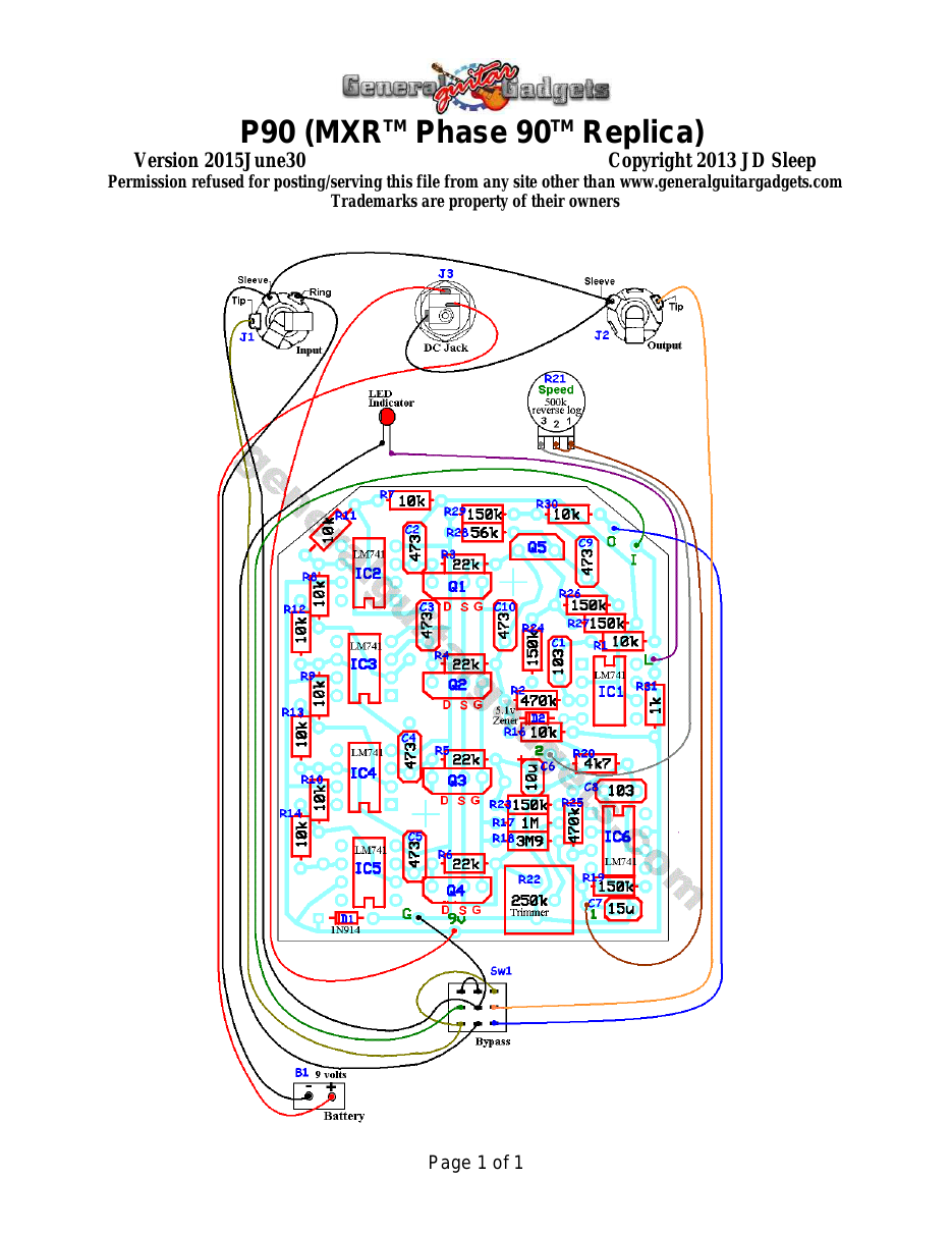
Parts Layout / Wiring Diagram
What you will need
Bill of Materials
Version 2012November19 · Copyright 2012 JD Sleep · Permission refused for posting/serving this file from any site other than www.generalguitargadgets.com · Trademarks are property of their owners
Resistors
| Resistor ID | Value | 3-band Marking | 4-band Marking |
|---|---|---|---|
| R1 | 10k | brown-black-orange | brown-black-black-red |
| R2 | 470k | yellow-violet-yellow | yellow-violet-black-orange |
| R3 | 22k | red-red-orange | red-red-black-red |
| R4 | 22k | red-red-orange | red-red-black-red |
| R5 | 22k | red-red-orange | red-red-black-red |
| R6 | 22k | red-red-orange | red-red-black-red |
| R7 | 10k | brown-black-orange | brown-black-black-red |
| R8 | 10k | brown-black-orange | brown-black-black-red |
| R9 | 10k | brown-black-orange | brown-black-black-red |
| R10 | 10k | brown-black-orange | brown-black-black-red |
| R11 | 10k | brown-black-orange | brown-black-black-red |
| R12 | 10k | brown-black-orange | brown-black-black-red |
| R13 | 10k | brown-black-orange | brown-black-black-red |
| R14 | 10k | brown-black-orange | brown-black-black-red |
| R15 | 22k | red-red-orange | red-red-black-red |
| R16 | 10k | brown-black-orange | brown-black-black-red |
| R17 | 1M | brown-black-green | brown-black-black-yellow |
| R18 | 3M9 (3.9M) | orange-white-green | orange-white-black-yellow |
| R19 | 150k | brown-green-yellow | brown-green-black-orange |
| R20 | 4k7 (4.7k) | yellow-violet-red | yellow-violet-black-brown |
| R21 | Speed Control Potentiometer | ||
| R22 | 250k Trimmer | ||
| R23 | 150k | brown-green-yellow | brown-green-black-orange |
| R24 | 150k | brown-green-yellow | brown-green-black-orange |
| R25 | 470k | yellow-violet-yellow | yellow-violet-black-orange |
| R26 | 150k | brown-green-yellow | brown-green-black-orange |
| R27 | 150k | brown-green-yellow | brown-green-black-orange |
| R28 | 56k | green-blue-orange | green-blue-black-red |
| R29 | 150k | brown-green-yellow | brown-green-black-orange |
| R30 | 10k | brown-black-orange | brown-black-black-red |
| R31 | 1k (current limiting for LED Bypass indicator) | brown-black-red | brown-black-black-brown |
| R32 | 1M5 (1.5M) (optional, for bypass switch click prevention) | brown-green-green | brown-green-black-yellow |
Capacitors
| Capacitor ID | Value | Type | Possible Marking |
|---|---|---|---|
| C1 | 0.01µF | Film | 103 |
| C2 | 0.047µF | Film | 473 |
| C3 | 0.047µF | Film | 473 |
| C4 | 0.047µF | Film | 473 |
| C5 | 0.047µF | Film | 473 |
| C6 | 10µF | Tantalum ( or Aluminum Electrolytic) | 10µF |
| C7 | 15µF | Tantalum ( or Aluminum Electrolytic) | 15µF |
| C8 | 0.01µF | Film | 103 |
| C9 | 0.047µF | Film | 473 |
| C10 | 0.047µF | Film | 473 |
Potentiometers
| Part ID | Value | Type |
|---|---|---|
| R21 - Speed Control | 500k | Reverse Log Taper (or 100k linear) |
| R22 - Phase tuning (trimmer) | 250k | Trimmer |
Other
| Part ID | Part Name |
|---|---|
| IC1, IC2, IC3, IC4, IC5, IC6 | LM741 (or other single opamp) |
| Q1, Q2, Q3, Q4 | 2N5952 Matched JFETs (or similar JFETs) |
| Q5 | 2N4125 (or 2N3906 or other similar PNP BJT transistor) |
| D1 | 1N914 or other similar diode “marking “F914” |
| D2 | 5.1 volt Zener diode Marking “F231B” |
| D3 | LED (status indicator optional) |
| J1 | Stereo quarter-inch jack |
| J2 | Mono quarter-inch jack |
| J3 | DC Jack |
| B1 | 9 volt battery (not included in the Kit) |
| Sw1 | Heavy Duty 3PDT foot switch 9v battery snap, Printed Circuit Board, 24 gauge stranded wire, Enclosure, Knob |
How to build it
Instructions
Version 2015June29 · Copyright 2013 JD Sleep · Permission refused for posting/serving this file from any site other than www.generalguitargadgets.com · Trademarks are property of their owners
This is a MXRTM Phase 90TM Script version Phase Shifter replica known here as the P90. Follow the Bill of Materials, the Layout diagram and General Build Instructions. Important Note: If you are building this to fit in a 1590B size enclosure, Do Not use IC Sockets. The ICs will have to be soldered directly onto the PCB due to space limitations. This replica has held to the original layout as much as possible and still offer some great modern “Non-tone-altering upgrades; 1) true-bypass with LED indicator 2) top layer trace to replace the wire jumper across the top of the originals (and the reissues). The original units had a 2N4125 PNP transistor, the kit includes 2N3906 PNP transistor. We don't believe that there is any sound difference in using the 2N3906 as a replacement. The Kit also includes four matched 2N5952 JFET transistors, as in the originals. There is an R15 resistor that is in some of the later Phase 90™'s. It is shown in the schematic, but is not shown in the layout because it is not in the Script version. There is a place for it, so you can added it. We added it in the one pictured below so you can see where it would be. It works either way. Notes to anyone who etched their own PCB: 1. You need to have a wire jumper on the top of the PCB as shown in the diagram on the project page. 2. If you use a 500k “C” (Reverse Taper) potentiometer, you should wire the pot as shown in the alternate wiring diagram.
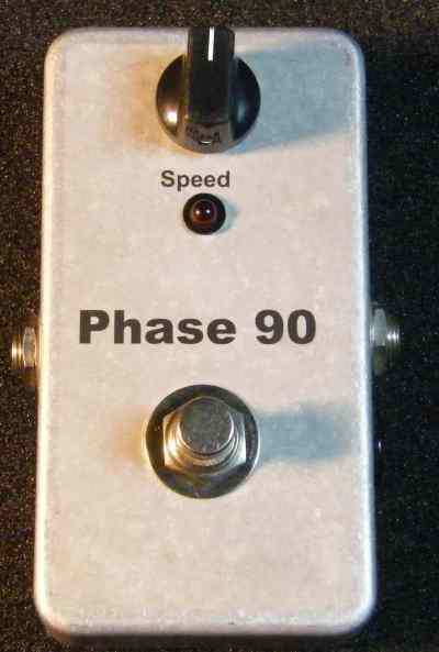
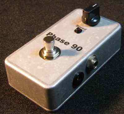
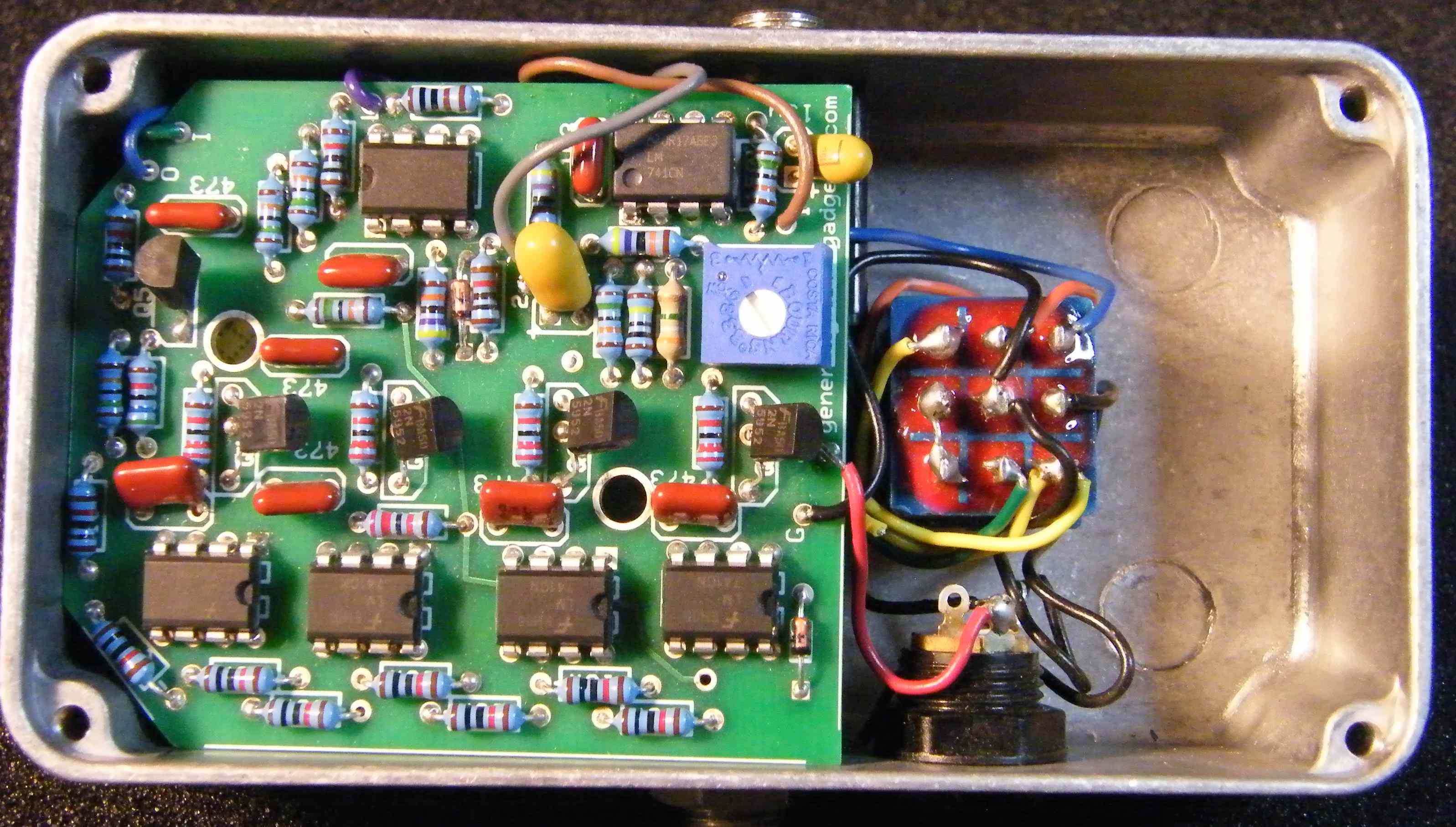
Here is a photo of the PCB and the inside of the box. Note that we didn't install a battery snap since we rarely use batteries.
Here are voltage readings taken from our prototype unit. The voltage on the Gate of the JFETS moves around some. Put the speed on lowest setting (full counter-closewise).
Component
Location
9 volt power supply Q2, Q3, Q4
Q5
Voltage
9v
Gate
2.5v plus or minus some
Source
5.0v
Drain
5.0v
Collector
4.3v
Base
3.7v
Emitter
2.6v
Pin 1
Less than 0.01v
Pin 2
Less than 0.01v
Pin 3
4.4v
Pin 4
0v
Pin 5
Less than 0.01v
Pin 6
4.4v
Pin 7
9v
Pin 8
0v
Pin 1
Less than 0.01v
Pin 2
5v
Pin 3
5v
Pin 4
0v
Pin 5
Less than 0.01v
Pin 6
2.1v
Pin 7
9v
Pin 8
0v
IC6
Pin 1
0v
(IC6 pin voltages vary
Pin 2
5v
with speed control)
Pin 3
4.7v
Pin 4
0v
Pin 5
0v
Pin 6
4v
Pin 7
9v
Pin 8
0v
IC1
IC2, IC3, IC4, IC5
Comments and questions are welcome and can be sent to [email protected]
More about this project
Notes, sounds and related links

Ready to build? We have the kit.
Buy a P90 Complete Kit. Includes all the parts and materials you need to build one, all for about the price you would pay for a PCB and parts.

Would you like a Ready to Solder Circuit Board for this project?
Note: If you buy the kit, the Ready-to-Solder Printed Circuit Board (RTS PCB) is included in the kit. You do not need to purchase this Ready to Solder Circuit Printed Board if you buy the kit.