
Project · Phase Shifters
MXR™ Phase 45™
This is the original MXR™ Phase 45™ Phase Shifter Replica known as P45. This is an excellent phase shifter for players who want a beautiful phase shifter sound without the irritating "pop music of the 1970's" sounds that some phase shifters have.
Project files
Everything you need to build it
Phase 45™ Ready-For-Transfer Printed Circuit Board Layout - For use only if you are a complete DIY person who wants to etch and drill your own PCB. Otherwise, we recommend you ignore this PCB mask and buy the Ready-to-Solder Printed Circuit Board or Complete Kit.
Schematic
Schematic
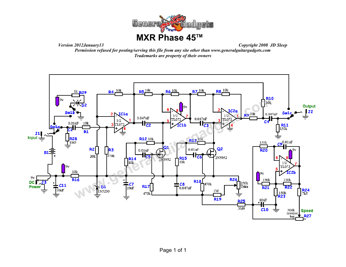
Parts layout
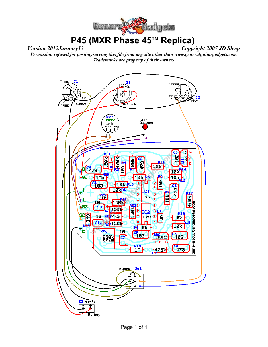
Parts Layout / Wiring Diagram
What you will need
Bill of Materials
Version 2009May26 · Copyright 2006 JD Sleep · Permission refused for posting/serving this file from any site other than www.generalguitargadgets.com · Trademarks are property of their owners
Resistors
| Resistor ID | Value | 3-band Marking | 4-band Marking |
|---|---|---|---|
| R1 | 10k | brown-black-orange | brown-black-black-red |
| R2 | 20k | red-black-orange | red-black-black-red |
| R3 | 470k | yellow-violet-yellow | yellow-violet-black-orange |
| R4 | 10k | brown-black-orange | brown-black-black-red |
| R5 | 10k | brown-black-orange | brown-black-black-red |
| R6 | 10k | brown-black-orange | brown-black-black-red |
| R7 | 10k | brown-black-orange | brown-black-black-red |
| R8 | 10k | brown-black-orange | brown-black-black-red |
| R9 | 10k | brown-black-orange | brown-black-black-red |
| R10 | 10k | brown-black-orange | brown-black-black-red |
| R11 | 150k | brown-green-yellow | brown-green-black-orange |
| R12 | 10k | brown-black-orange | brown-black-black-red |
| R13 | 10k | brown-black-orange | brown-black-black-red |
| R14 | 10k | brown-black-orange | brown-black-black-red |
| R15 | 10k | brown-black-orange | brown-black-black-red |
| R16 | 10k | brown-black-orange | brown-black-black-red |
| R17 | 470k | yellow-violet-yellow | yellow-violet-black-orange |
| R18 | 470k | yellow-violet-yellow | yellow-violet-black-orange |
| R19 | 1M | brown-black-green | brown-black-black-yellow |
| R20 | 150k | brown-green-yellow | brown-green-black-orange |
| R21 | 150k | brown-green-yellow | brown-green-black-orange |
| R22 | 150k | brown-green-yellow | brown-green-black-orange |
| R23 | 150k | brown-green-yellow | brown-green-black-orange |
| R24 | 7k5 | violet-green-red | violet-green-black-brown |
| R25 | 3M9 (3.9M) | orange-white-green | orange-white-black-yellow |
| R26 | 250k Trimmer | ||
| R27 | Speed Control Potentiometer | ||
| R28 | 1M5 (1.5M) (optional for bypass switch click prevention) | brown-green-green | brown-green-black-yellow |
| R29 | 1k (for optional LED Bypass indicator) | brown-black-red | brown-black-black-brown |
Capacitors
| Capacitor ID | Value | Type | Possible Marking |
|---|---|---|---|
| C1 | 0.01µF | Film | 103 |
| C2 | 0.047µF | Film | 473 |
| C3 | 0.047µF | Film | 473 |
| C4 | 0.047µF | Film | 473 |
| C5 | 0.01µF | Film | 103 |
| C6 | 0.01µF | Film | 103 |
| C7 | 10µF | Tantalum ( or Aluminum Electrolytic) | 10µF |
| C8 | 0.047µF | Film | 473 |
| C9 | 0.01µF | Film | 103 |
| C10 | 10µF | Tantalum ( or Aluminum Electrolytic) | 10µF |
| C11 | 10µF | Tantalum ( or Aluminum Electrolytic) | 10µF |
Potentiometers
| Part ID | Value | Type |
|---|---|---|
| R26 - Phase tuning (trimmer) | 250k | Trimmer |
| R27 - Speed Control | 500k | Reverse Log Taper (or 100k linear) |
Other
| Part ID | Part Name |
|---|---|
| IC1, IC2 | TL072 (or other dual opamp) |
| Q1, Q2 | 2N5952 Matched JFETs (or similar JFETs) |
| D1 | 1N5230 (or other 4.7volt Zener diode) |
| D2 | LED (status indicator optional) |
| J1 | Stereo quarter-inch jack |
| J2 | Mono quarter-inch jack |
| J3 | DC Jack |
| B1 | 9 volt battery (not included in the Kit) |
Sw1 Heavy Duty 3PDT foot switch 9v battery snap, Printed Circuit Board, 24 gauge stranded wire, Enclosure, Knobs
How to build it
Instructions
Version 2015August19 · Copyright 2006, 2015 JD Sleep · Permission refused for posting/serving this file from any site other than www.generalguitargadgets.com · Trademarks are property of their owners
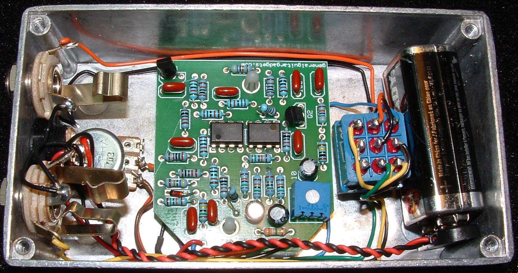
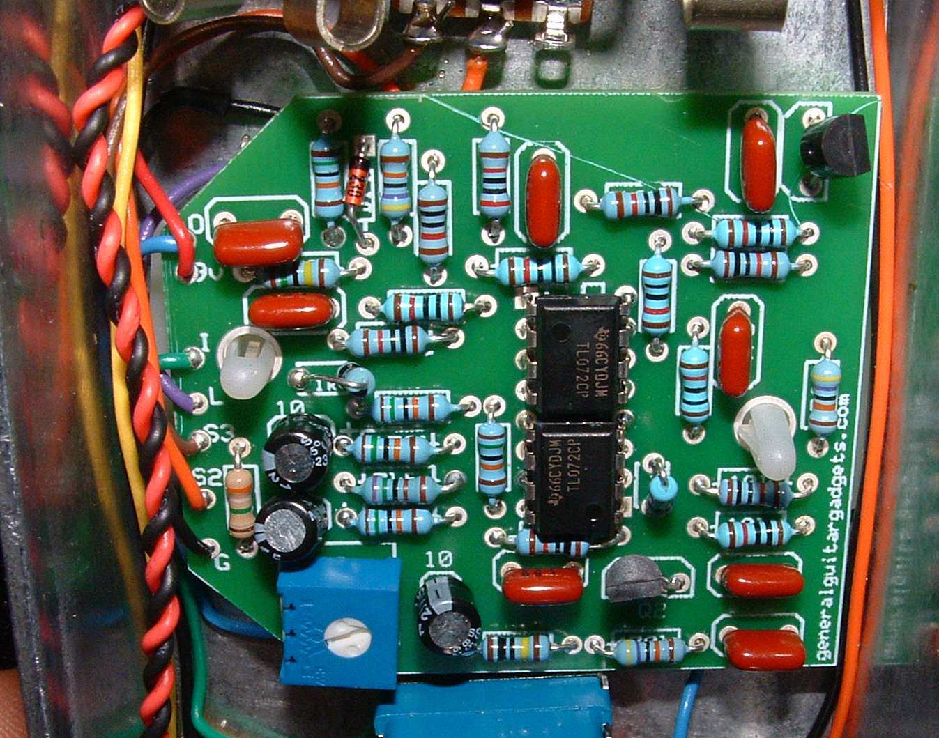
This is a replica of the MXRTM Phase 45TM referred to as P45 in these documents. This is a replica of the original, vintage, real MXRTM unit, not the DunlopTM reissue. This is an under-rated and a most excellent phase shifter. Sometimes wrongly written off as "too subtle", with the properly tuned JFETs, it is just a beautiful sounding phase shifter. Use the project documents provided, starting with the General Build Instructions. It will fit in a 1590B or similar enclosure, with a little planning, although you would have to use plastic enclosed jacks and fit the PCB over those. The kit and photos here are of a 125B enclosure to make it easier to fit together. If you use the 1590B or 1290B, the holes for the jacks need to be drilled as close to the top of the enclosure as possible and enclosed jacks should be used so that the populated PCB will fit over the jacks as the original did. The JFETS need to be matched. You can use the information at the geofex.com site to do that. The kit comes with a great sounding set of matched 2N5485 transistors. The original units had 2N5952 JFET transistors. Note that the pin out of these transistors may very. The 2N5952 will probably have to installed backwards from what the layout shows. When the unit is completely assembled, plug it in and adjust the trimmer for the best
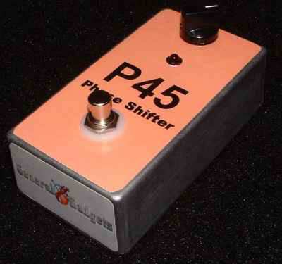
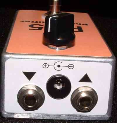
sounding phase shift. You will definitely hear the sweet spot in the trimmer setting. Following are some photos of the inside of the unit. Comments and questions are welcome and can be sent to [email protected]
Component
Location
9 volt power supply Q1
Q2
IC1
IC2
Voltage
9.4v
Gate
2.2v plus or minus some
Source
4.0v
Drain
4.0v
Gate
2.2v plus or minus some
Source
4.0v
Drain
4.0v
Pin 1
4.0v
Pin 2
4.0v
Pin 3
3.8v
Pin 4
0v
Pin 5
4.0v
Pin 6
4.0v
Pin 7
4.0v
Pin 8
9.4v
Pin 1
4.0v
Pin 2
4.0v
Pin 3
Varies with Speed Control
Pin 4
0v
Pin 5
Varies with Speed Control
Pin 6
Varies with Speed Control
Pin 7
Varies with Speed Control
Pin 8
9.4
Make it your own
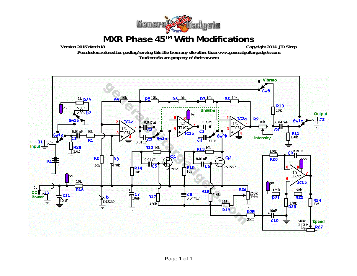
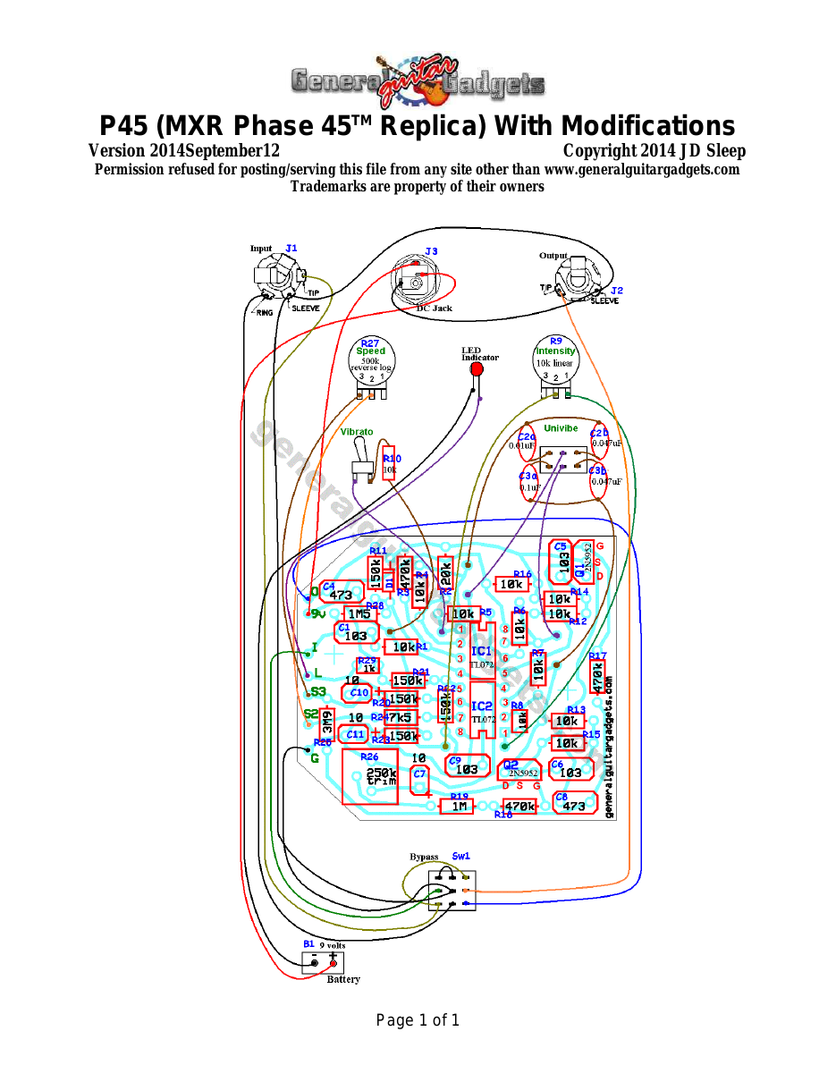
Modification Instructions
Version 2014September12 · Copyright 2014 JD Sleep · Permission refused for posting/serving this file from any site other than www.generalguitargadgets.com · Trademarks are property of their owners
These are instructions for some of the many modifications that you can make to your MXR™ Phase 45™ project. These modifications are based on modifications by J.C. Maillet that have been posted on his site for years. We did some modifications to his modifications. We found that his modification #5 “Mix” control did not work as we expected and is difficult to tune it in to vibrato or intensity. So we provide some alternatives here. Modification 1: Add an Intensity Control. To do this you will replace Resistor R9 (10k value) with a 10k linear taper pot. Wire it has shown in the Modifications Wiring Diagram. This seems like a strange way to control the intensity of the phase effect, but we found that lowering the resistance here fades out the phase smoothly and this is the most straight forward simple method we found to do that. Another option is to add a 100k pot after R9 and as you raise the resistance, the phase effect will also fade. We found the 100k pot solution to not have as smooth of control as the 10k pot we implemented. Modification 2: UniVibe Me! This is the most awesome of all the modifications. This really works well. Just replace Caps C2 and C3 with 10 to 1 value ratio, a 0.1uF and 0.01uF cap and you get a more pulsing effect very similar to a UniVibe. The modification can be a replacement of the caps to have a permanent UniVibe-type effect, or as we have shown in the wiring diagram and schematic you can make it switchable from stock Phase Shifter to “UniVibe Mode”. Modification 3: Vibrato Mode Control. The sound of “Phase Shifter” is created by mixing a warbled sound with the dry sound. If we remove the dry sound, you are left with a warbly pitch-vibrato sound. We have found that phase shifters usually don't give a very strong vibrato when you cut the dry mix and this is the case with the Phase 45™. We have included the mod here because some folks might like the subtle effect and want to know how to do it. To Implement, just cut the dry signal line and put in a simple on/off switch to be able to switch the dry signal in/out as we did with Sw3 in the schematic and diagram. We hope you enjoy tinkering with this beautiful effect stompbox!

More about this project
Notes, sounds and related links
Here is some modification information that can be applied to this Phase 45™ project.

Here's a demo of the P45 "Univibe™" Modification as listed above
Ready to build? We have the kit.
Buy a Phase 45™ Complete Kit. Includes all the parts and materials you need to build one, all for about the price you would pay for a PCB and parts.

Would you like a Ready to Solder Circuit Board for this project?
Note: If you buy the kit, the Ready-to-Solder Printed Circuit Board (RTS PCB) is included in the kit. You do not need to purchase this Ready to Solder Circuit Printed Board if you buy the kit.