
Project · Filters (Envelope)
Musitronics™ Mu-tron™ III (Neutron)
This is a Musitronics™ Mutron III replica project called the Neutron. This project is from the GEOFEX site (note: this external site does not use a secure HTTPS connection). Based on one of the most famous and best sounding Envelope Filters ever made.. Trademarks mentioned here belong to their owners not to General Guitar Gadgets.
Special notes:
Project files
Everything you need to build it
Neutron Ready-For-Transfer to Printed Circuit Board - For use only if you are a complete DIY person who wants to etch and drill your own PCB. Otherwise, we recommend you ignore this PCB mask and buy the Ready-to-Solder Printed Circuit Board or Complete Kit from the links below.
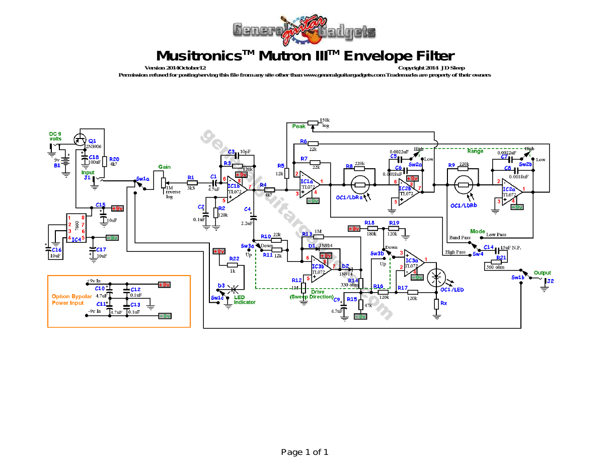
Parts layout
Parts Layout / Wiring Diagram
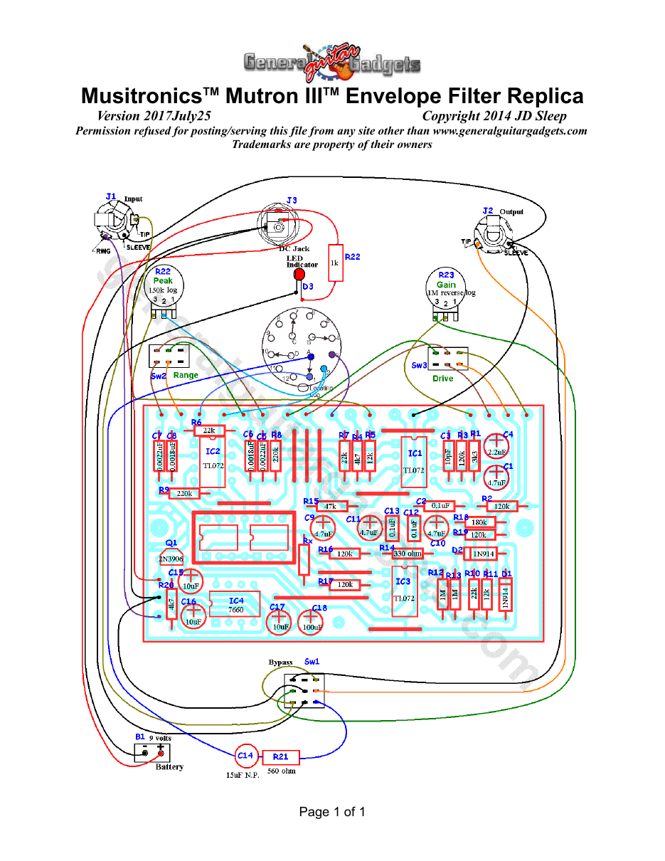
What you will need
Bill of Materials
Version 2014October12 · Copyright 2014 JD Sleep · Permission refused for posting/serving this file from any site other than www.generalguitargadgets.com · Trademarks are property of their owners
Resistors
| Resistor ID | Value | 3-band Marking | 4-band Marking |
|---|---|---|---|
| R1 | 3k3 (3.3k) | orange-orange-red | orange-orange-black-brown |
| R2 | 120k | brown-red-yellow | brown-red-black-orange |
| R3 | 120k | brown-red-yellow | brown-red-black-orange |
| R4 | 4k7 (4.7k) | yellow-violet-red | yellow-violet-black-brown |
| R5 | 12k | brown-red-orange | brown-red-black-red |
| R6 | 22k | red-red-orange | red-red-black-red |
| R7 | 22k | red-red-orange | red-red-black-red |
| R8 | 220k | red-red-yellow | red-red-black-orange |
| R9 | 220k | red-red-yellow | red-red-black-orange |
| R10 | 22k | red-red-orange | red-red-black-red |
| R11 | 12k | brown-red-orange | brown-red-black-red |
| R12 | 1M | brown-black-green | brown-black-black-yellow |
| R13 | 1M | brown-black-green | brown-black-black-yellow |
| R14 | 330 ohm | orange-orange-brown | orange-orange-black-black |
| R15 | 47k | yellow-violet-orange | yellow-violet-black-red |
| Rx | See instructions | ||
| R16 | 120k | brown-red-yellow | brown-red-black-orange |
| R17 | 120k | brown-red-yellow | brown-red-black-orange |
| R18 | 180k | brown-gray-yellow | brown-gray-black-orange |
| R19 | 120k | brown-red-yellow | brown-red-black-orange |
| R20 | 4k7 (4.7k) | yellow-violet-red | yellow-violet-black-brown |
| R21 | 560 ohm | green-blue-brown | green-blue-black-black |
Capacitors
| Capacitor ID | Value | Type | Possible Marking |
|---|---|---|---|
| C1 | 4.7µF | Tantalum | 4µ7 |
| C2 | 0.1µF | Film or Ceramic | 104 |
| C3 | 10pF | Ceramic | 100 or 10 |
| C4 | 2.2µF | Aluminum Electrolytic | 2.2uF |
| C5 | 0.0022µF | Film | 222 or 22n |
| C6 | 0.0018µF | Film | 182 |
| C7 | 0.0022µF | Film | 222 or 22n |
| C8 | 0.0018µF | Film | 182 |
| C9 | 4.7µF | Aluminum Electrolytic | 4µ7 |
| C10 | 4.7µF | Aluminum Electrolytic | 4µ7 |
| C11 | 4.7µF | Aluminum Electrolytic | 4µ7 |
| C12 | 0.1µF | Film or Ceramic | 104 |
| C13 | 0.1µF | Film or Ceramic | 104 |
| C14 | 15µF non polar | Aluminum Electrolytic | 15uF |
| C15 | 10µF | Aluminum Electrolytic | 10uF |
| C16 | 10µF | Aluminum Electrolytic | 10uF |
| C17 | 10µF | Aluminum Electrolytic | 10uF |
| C18 | 100µF | Aluminum Electrolytic | 100uF |
Potentiometers
| Part ID | Value | Type |
|---|---|---|
| VR1 - Gain Control | 1M | Reverse Log Taper |
| VR2- Peak Control | 150k | Log (or Audio) Taper |
Other
| Part ID | Part Name |
|---|---|
| IC1, IC2, IC3 | TL072 |
| IC4 | 7660 Charge Pump IC (or MAX1044 - see instructions) |
| D1, D2 | 1N914 |
| D3 | LED |
| Q1 | 2N3906 |
| LDR/LED | Dual LDR/LED unit (see instructions) |
| J1 | Stereo quarter-inch jack |
| J2 | Mono quarter-inch jack |
| J3 | DC Jack |
| B1 | 9 volt battery |
| Sw1 | Heavy Duty 3PDT foot switch |
| Sw2 | DPDT On-On Mini Toggle Switch |
| Sw3 | DPDT On-On Mini Toggle Switch |
| Sw4 | 1-Pole 3-way rotarty switch (can be more than 1 pole, but only one is used) 9v battery snap, Printed Circuit Board, 24 gauge stranded wire, Enclosure, Knobs, Rubber Feet, PCB Standoffs |
More about this project
Notes, sounds and related links
- Most of the optical units that we found to work well with this circuit are now obsolete. If you know of any solutions that work well for the LED/LDR unit, let us know and we can test it and post it on this page.
- If you experience noise from the Charge Pump, Connecting pin 1 and 8 of the 7660 IC with a jumper may stop the whine noise from that charge pump IC.
Project files:

Ready to build? We have the kit.
Would you like a Ready to Solder Circuit Board for this project?