
Project · Filters (Envelope)
Maestro™ Filter Sample/Hold
Here's something a little different. It's a synthesizer Voltage Controlled Filter module (envelope filter) and a Sample & Hold module all in a stompox suitable for guitar (and other instruments). This is listed as Maestro™ Filter Sample/Hold, but it is exactly the same circuit as the Oberheim Voltage Controlled Filter. The envelope filter on this unit is excellent for guitar and bass. Of course the main attraction is the sample & hold, which is rare to find in a stompbox for guitar (or bass). A big Thanks to Rick Lawerence, R.G. Keen and Aron Nelson for helping make this project happen! Any trademarks mention on this page belong to their rightful owners and not to General Guitar Gadgets.
A note about the Noise Transistor (Q4) selection:
The Schematic lists it as a 2N3904. While testing transistors in boosters we noticed that we had a batch of BC182L transistors that had a lot of background hiss. As expected, these transistors work well as "noise" transistors, so the kit uses one of these BC182L transistors for Q4 and it is the best transistor we have found for Q4. A bad transistor is hard to find these days!
Project files
Everything you need to build it
Maestro™ Filter Sample/Hold Replica Ready-For-Transfer Printed Circuit Board Layout
Schematic
Schematic
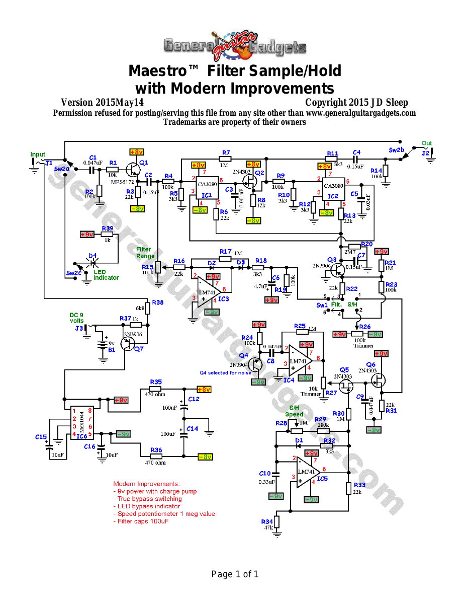
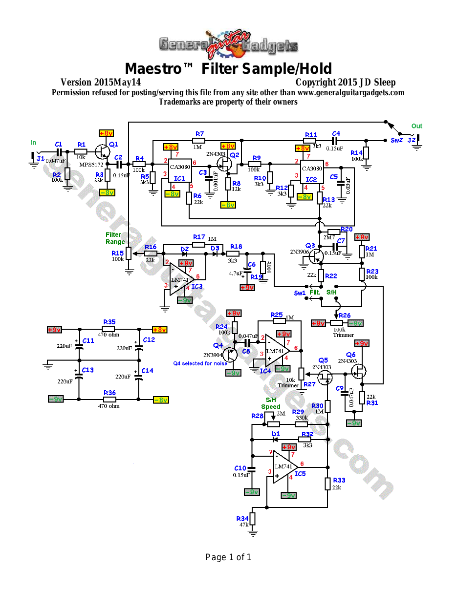
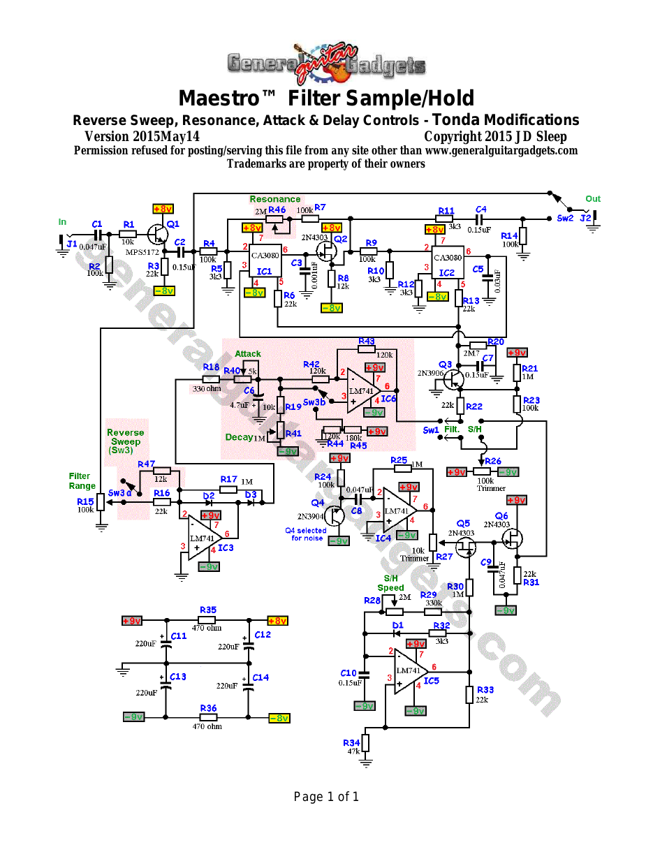
Parts layout
Parts Layout / Wiring Diagram
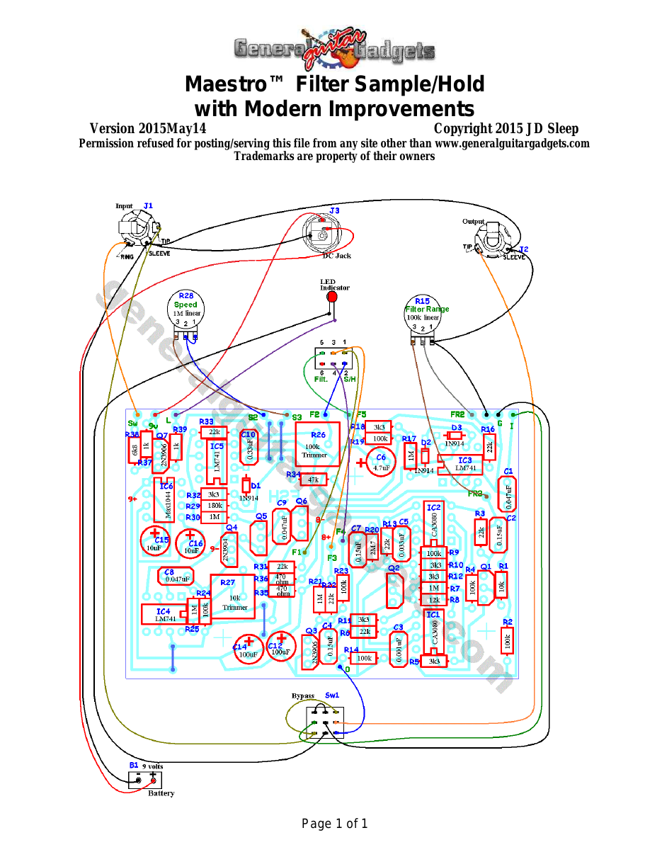
What you will need
Bill of Materials
Version 2018December30 · Copyright 2015, 2018 JD Sleep · Permission refused for posting/serving this file from any site other than www.generalguitargadgets.com · Trademarks are property of their owners
Resistors
| Resistor ID | Value | 3-band Marking | 4-band Marking |
|---|---|---|---|
| R1 | 10k | brown-black-orange | brown-black-black-red |
| R2 | 100k | brown-black-yellow | brown-black-black-orange |
| R3 | 22k | red-red-orange | red-red-black-red |
| R4 | 100k | brown-black-yellow | brown-black-black-orange |
| R5 | 3k3 (3.3k) | orange-orange-red | orange-orange-black-brown |
| R6 | 22k | red-red-orange | red-red-black-red |
| R7 | 1M | brown-black-green | brown-black-black-yellow |
| R8 | 12k | brown-red-orange | brown-red-black-red |
| R9 | 100k | brown-black-yellow | brown-black-black-orange |
| R10 | 3k3 (3.3k) | orange-orange-red | orange-orange-black-brown |
| R11 | 3k3 (3.3k) | orange-orange-red | orange-orange-black-brown |
| R12 | 3k3 (3.3k) | orange-orange-red | orange-orange-black-brown |
| R13 | 22k | red-red-orange | red-red-black-red |
| R14 | 100k | brown-black-yellow | brown-black-black-orange |
| R15 (Filter Range Potentiometer) | 100k Linear | ||
| R16 | 22k | red-red-orange | red-red-black-red |
| R17 | 1M | brown-black-green | brown-black-black-yellow |
| R18 | 3k3 (3.3k) | orange-orange-red | orange-orange-black-brown |
| R19 | 100k | brown-black-yellow | brown-black-black-orange |
| R20 | 2M7 | red-violet-green | red-violet-black-yellow |
| R21 | 1M | brown-black-green | brown-black-black-yellow |
| R22 | 22k | red-red-orange | red-red-black-red |
| R23 | 100k | brown-black-yellow | brown-black-black-orange |
| R24 | 100k | brown-black-yellow | brown-black-black-orange |
| R25 | 1M | brown-black-green | brown-black-black-yellow |
| R26 | 100k trimmer | ||
| R27 | 10k trimmer | ||
| R28 (Speed Control Potentiometer) | 1M linear | ||
| R29 | 180k | brown-gray-yellow | brown-gray-black-orange |
| R30 | 1M | brown-black-green | brown-black-black-yellow |
| R31 | 22k | red-red-orange | red-red-black-red |
| R32 | 3k3 (3.3k) | orange-orange-red | orange-orange-black-brown |
| R33 | 22k | red-red-orange | red-red-black-red |
| R34 | 47k | yellow-violet-orange | yellow-violet-black-red |
| R35 | 470 ohm | yellow-violet-brown | yellow-violet-black-black |
| R36 | 470 ohm | yellow-violet-brown | yellow-violet-black-black |
| R37 | 1k | brown-black-red | brown-black-black-brown |
| R38 | 6k8 (6.8k) | blue-gray-red | blue-gray-black-brown |
| R39 | 1k | brown-black-red | brown-black-black-brown |
Capacitors
| Capacitor ID | Value | Type | Possible Marking |
|---|---|---|---|
| C1 | 0.047µF | Film | 473 |
| C2 | 0.15µF | Film | 154 |
| C3 | 0.001µF | Film | 102 |
| C4 | 0.15µF | Film | 154 |
| C5 | 0.033µF | Film | 333 |
| C6 | 4.7µF | Aluminum Electrolytic | 4.7µF |
| C7 | 0.15µF | Film | 154 |
| C8 | 0.047µF | Film | 473 |
| C9 | 0.047µF | Film | 473 |
| C10 | 0.33µF | Film | 334 |
| C11 | none | ||
| C12 | 100µF | Aluminum Electrolytic | 100µF |
| C13 | none | ||
| C14 | 100µF | Aluminum Electrolytic | 100µF |
| C15 | 10µF | Aluminum Electrolytic | 10µF |
| C16 | 10µF | Aluminum Electrolytic | 10µF |
Potentiometers
| Part ID | Value | Type |
|---|---|---|
| R15 – Filter Range Control | 100k | Linear Taper |
| R28 - Speed Control | 1M | Linear Taper |
| R26 – 100k Trimmer | 100k | Trimmer |
| R27 – 10k Trimmer | 10k | Trimmer |
Other
| Part ID | Part Name |
|---|---|
| IC1 | CA3080 |
| IC2 | CA3080 |
| IC3 | LM741 |
| IC4 | LM741 |
| IC5 | LM741 |
| IC6 | MAX1044 |
| Q1 | 2N5088 or 2N5089 Transistor |
| Q2 | 2N5457 |
| Q3 | 2N3906 or Other Low gain PNP Transistor |
| Q4 | 2N3904 or best noise transistor |
| Q5 | 2N5457 |
| Q6 | 2N5457 |
| Q7 | 2N3906 or Other PNP Transistor |
| D1 | 1N914 |
| D2 | 1N914 |
| D3 | 1N914 |
| D4 | Status Indicator LED and holder |
| J1 | Stereo quarter-inch jack |
| J2 | Mono quarter-inch jack |
| J3 | DC Jack |
| B1 | 9 volt battery (not included in the Kit) |
| Sw1 | Heavy Duty 3PDT foot switch |
9v battery snap, Printed Circuit Board, 24 gauge stranded wire, Enclosure
How to build it
Instructions
Version 2019August25 · Copyright 2018 JD Sleep · Permission refused for posting/serving this file from any site other than www.generalguitargadgets.com · Trademarks are property of their owners
This is a replica of the Maestro™ Filter Sample/Hold. Referred to as FSH in these documents. This exact circuit with the same PCB and enclosure (with different graphics) was also released as the Oberheim Voltage Controlled Filter. Both were released in the mid to late 1970’s. This pedal has a great Envelope Follower Filter (sometimes known as voltage controlled filter or auto wah) and has a cool Sample/Hold (S/H) setting as well. Keep in mind that Sample & Hold circuits were originally designed to be used on a synthesizer oscillator output which, when S&H is engaged, typically is set to an entirely different ADRS (Attack, Decay, Release Sustain) sound than a guitar output has. Due to the very nature of this effect, a lengthened sustain sound is needed to hear the S/H at its best. In order to get the best S/H sound on guitar, it is recommend that you place it after a compressor or distortion/fuzz (some volume boost may help as well) in your signal chain. Any compressor that has a “Level” or “Volume” control will work. Also distortion or fuzz before it will usually give a better sustained sound that will work well. Setting the Trimmers You have to set the trimmers by ear. It takes a bit of time, but it's not difficult to tune it in. The two trimmers only affect the Sample & Hold (S&H) function (mode). Set the toggle switch in S&H mode. The Range control setting has no bearing on the S&H sound, so the setting of the Range knob doesn't matter. It's best to turn the Speed
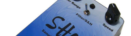
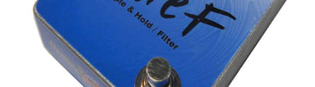

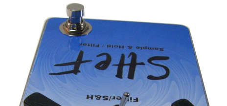
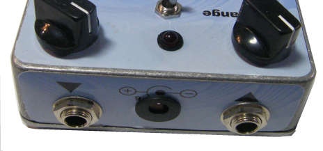
Knob up pretty high (fast) when you are setting the trimmers so that you can hear the effect at its best. Plug the unit in and hit guitar notes to hear the sound. You will need some long sustain from your input for ease in setting it up, so you may have to precede the unit with a fuzz or heavy overdrive sound. You will have to tweak both trimmers in combination. Tune them to what sounds best to your ear. Use the project documents provided, starting with the General Build Instructions. Refer to the FSH Project for reference. Here’s a photo of the insides of the FSH. Note the photo below is of the prototype and has some inline transistor sockets that are not included in the kit.






Here are some voltage readings that my be helpful if you have problems with your FSH build. Please note that some of the voltages have a negative value. Note that you may not get these exact values, but this is a general guideline.
Component
Location
Voltage
IC1 (CA3080)
Pin 1
0v
Pin 2
0v
Pin 3
0v
Pin 4
-8.8v
Pin 5
-8.2v
Pin 6
-1.2v
Pin 7
9.0v
Pin 8
0v
Pin 1
0v
Pin 2
0v
Pin 3
0v
Pin 4
-8.8v
Pin 5
-8.2v
Pin 6
-1.2v
Pin 7
9v
Pin 8
0v
Pin 1
-9.0v
Pin 2
0v
Pin 3
0v
Pin 4
-9.0v
Pin 5
-9.0v
Pin 6
-0.1v
Pin 7
9.0v
IC2 (CA3080)
IC3 (LM741)
IC4 (LM741)
IC5 (LM741)
IC6 (MAX1044)
Q1
Pin 8
0v
Pin 1
-9.0v
Pin 2
0v
Pin 3
0v
Pin 4
-9.0v
Pin 5
-9.0v
Pin 6
0v
Pin 7
9.0v
Pin 8
0v
Pin 1
-9.0v
Pin 2
(Oscillates)
Pin 3
-5.4v
Pin 4
-9.0v
Pin 5
-9.0v
Pin 6
-8.0v
Pin 7
9.0v
Pin 8
0v
Pin 1
9.0v
Pin 2
4.5v
Pin 3
0v
Pin 4
-4.5v
Pin 5
-9.0v
Pin 6
4.5v
Pin 7
7.3v
Pin 8
9.0v
Collector
9.0v
Base
0.05v
Emitter
0.6v
Q2
Q3
Q4
Q5
Q6
Q7
Gate
-1v
Source
0.05v
Drain
9.0v
Collector
0.5v
Base
0v
Emitter
-8.0v
Collector
-9.0v
Base
-0.1v
Emitter
-0.1v
Gate
0v
Source
Oscillates 1.0v
Drain
-7.0v
Gate
9.0v
Source
-2.6v
Drain
Oscillates 1.0v
Collector
9.0v
Base
9.0v
Emitter
9.0v
Comments and questions are welcome and can be sent to [email protected]
More about this project
Notes, sounds and related links
Here are a couple of other schematics for reference. One is the schematic of the original unit. The other schematic includes some modifications highlighted in pink. Some of the mods can be added to the existing board with no changes to the board. The "Reverse Direction" mod, that reverses the sweep, requires an extra IC and associated parts that can be built on a small board and wired into the main board.


Ready to build? We have the kit.
Buy a Maestro™ Filter Sample and Hold Replcia™ Complete Kit. Includes all the parts and materials you need to build one, all for about the price you would pay for a PCB and parts. 
Would you like a Ready to Solder Circuit Board for this project? Note: If you buy the kit, the Ready-to-Solder Printed Circuit Board (RTS PCB) is included in the kit. You do not need to purchase this Ready to Solder Circuit Printed Board if you buy the kit.