
Project · Distortion
Red Fuzz
This is the Red Fuzz project based on the schematic from Robin Tomtlund's Effects. This is a very nice distortion pedal (even though then name says "Fuzz"). similar in some ways to the DOD™ 250 Overdrive but with a very nice "Rat™-Style" tone control.
Project files
Everything you need to build it
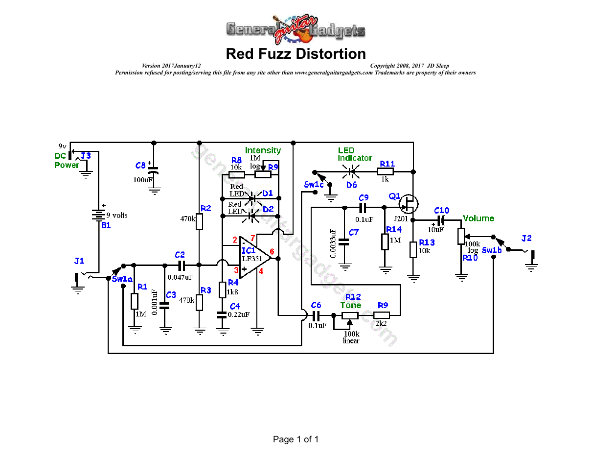
Parts layout
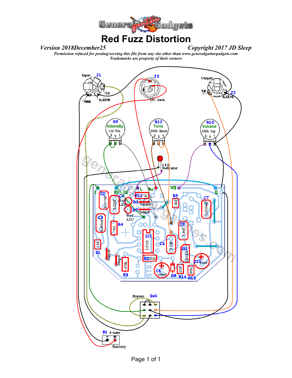
Parts Layout / Wiring Diagram
What you will need
Bill of Materials
Version 2017November17 · Copyright 2017 JD Sleep · Permission refused for posting/serving this file from any site other than www.generalguitargadgets.com · Trademarks are property of their owners
Resistors
| Resistor ID | Value | 3-band Marking | 4-band Marking |
|---|---|---|---|
| R1 | 1M | brown-black-green | brown-black-black-yellow |
| R2 | 470k | yellow-violet-yellow | yellow-violet-black-orange |
| R3 | 470k | yellow-violet-yellow | yellow-violet-black-orange |
| R4 | 1k8 (1.8k) | brown-gray-red | brown-gray-black-brown |
| R5 | none | ||
| R6 | none | ||
| R7 | none | ||
| R8 | 10k | brown-black-orange | brown-black-black-red |
| R9 | 2k2 (2.2k) | red-red-red | red-red-black-brown |
| R10 (Volume Control) | 100k Log Potentiometer | ||
| R11 | 1k | brown-black-red | brown-black-black-brown |
| R12 (Tone Control) | 100k Linear Potentiometer | ||
| R13 (Intensity Control) | 1M Log Potentiometer |
Capacitors
| Capacitor ID | Value | Type | Possible Marking |
|---|---|---|---|
| C1 | none | ||
| C2 | 0.047µF | Film | 473 |
| C3 | 0.001µF | Film | 102 or 1n |
| C4 | 0.22µF | Film | 224 |
| C5 | none | ||
| C6 | 0.1µF | Film or Ceramic | 104 or µ1xxx |
| C7 | 0.0033µF | Film | 332 or 3n3 |
| C8 | 100µF | Aluminum Electrolytic | 100µF |
| C9 | 0.1µF | Film or Ceramic | 104 or µ1xxx |
| C10 | 10µF | Aluminum Electrolytic or Tant | 10µF |
Potentiometers
| Part ID | Value | Type |
|---|---|---|
| R8 - Gain | 500k | Reverse Log Taper Potentiometer |
| R10 - Volume | 100k | Log (Audio) Taper Potentiometer |
Other
| Part ID | Part Name |
|---|---|
| IC1 | LM351 Opamp |
| D1 | 1N914 or other clipping device |
| D2 | 1N914 or other clipping device |
| D6 | Status Indicator LED and holder |
| D8 (optional) Reverse Power Protection | 1N4001 or 1N914 |
| J1 | Stereo quarter-inch jack |
| J2 | Mono quarter-inch jack |
| J3 | DC Jack |
| B1 | 9 volt battery (not included in the Kit) |
| Sw1 | Heavy Duty 3PDT foot switch 9v battery snap, Printed Circuit Board 24 gauge stranded wire, Enclosure, Knobs |
How to build it
Instructions
Version 2017November17 · Copyright 2017 JD Sleep · Permission refused for posting/serving this file from any site other than www.generalguitargadgets.com · Trademarks are property of their owners
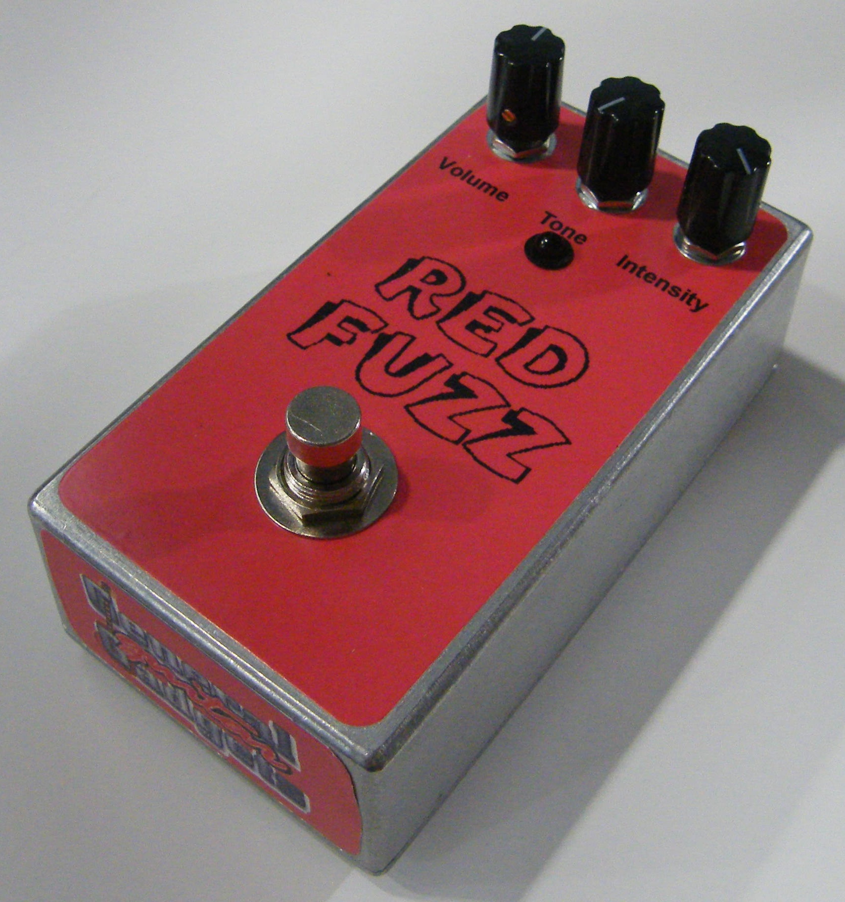
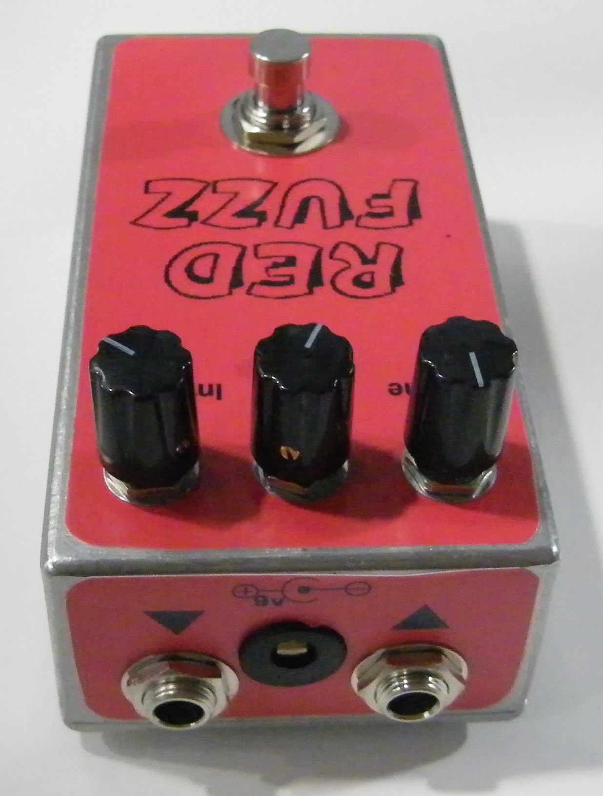
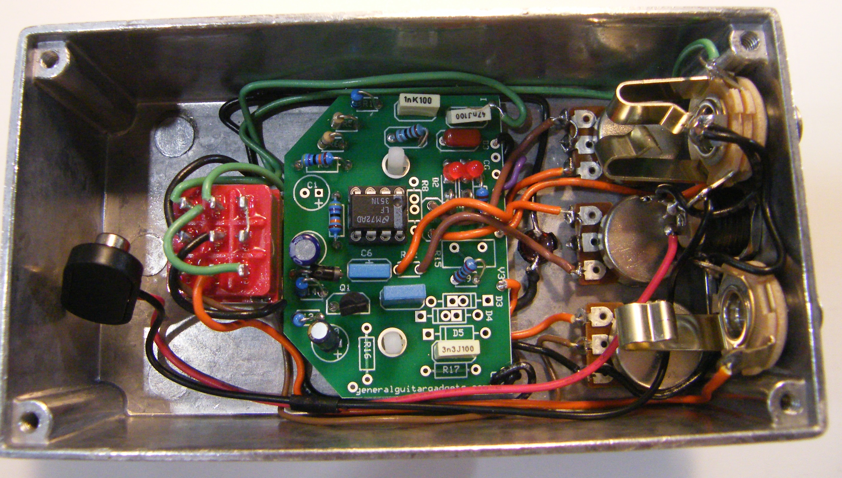
This is the Famous Red Fuzz, it should be famous to DIY stompbox builders anyway. It was posted decades ago on a website hosted by Robin Tomtlund. It is actually a distortion that was sort of mis-labeled, but back in those days there wasn’t such a distinction between Fuzz, Distortion and Overdrive. Actually I still don’t know the difference. At any rate, this is an awesome distortion pedal, similar to the Distortion Plus™/DOD™ 250, but with the addition of a Rat™-style tone control. Use the project documents provided, starting with the General Build Instructions. Follow the layout diagrams to add components to the PCB and the wiring diagrams to hook it all up. There are photos in this document to give some ideas of the overall layout and wiring. Comments and questions are welcome and can be sent to [email protected] Here is a chart of voltages taken at the IC pins. This information can be used to help you find and fix problems if your Red Fuzz doesn't work when you test it. These are approximate voltages, if yours are within one volt variance, you are probably okay.
Component
Location
9 volt power supply IC1
Voltage
9v
Pin 1
0.1v
Pin 2
4.5v
Pin 3
3.6v
Pin 4
0v
Pin 5
0.1v
Pin 6
4.5v
Pin 7
9v
Pin 8
0v
Here's a look inside:
More about this project
Notes, sounds and related links
- Red Fuzz Addition Information - Provided by Tobias Karlsson. These diagrams show the IC and transistor pinouts and voltages. Thanks Tobias!
- Red Fuzz Modification - Diode switching mod by Tobias Karlsson.


Here are some sound files of this effect, contributed by Tobias Karlsson.
Notes from Tobias about the sound files:
Red Fuzz LEDS - Fender™ Stratocaster™ (single coils, rosewood fingerboard) using bridge or neck coil with full volume and tone, into the "Red Fuzz" with full "Tone" (towards the treble) and full "Intensity", into a Marshall™ Super Lead 100w -72 with 4x12" cab with "greenbacks". Recording mic is Shure SM57 (a rather close up to the cab)
Red Fuzz SILICON - Same setup as with the LEDS recording except for instead of LED's, there are two 1N4148 silicon diodes.
No distortion is created by the amp and recording volume was quite low. No "EQ-ing" in the computer or any kind of effects anywhere as I think that's a fair way to demonstrate an effect pedal. I tried to play in the same style in both recordings and using almost the same licks so a comparison can be made easy between them. When using it with the LEDs and turning down "Intensity" it could be used to boost up some distortion in the amp, using it as a semi clean booster, the output is "big". And of course, the noise level is bigger when using the silicon (and output is smaller) but I didn't record that as I thought it depends to much of the amp what sound that will produce. I?m not sure if I made the "Red Fuzz" justice with my recording and guitar playing but I hope you find the samples useful anyway, at least you get an idea about how it sounds. I didn't have so much time experimenting where to place the mic to get the best tone (or so the tone that is coming out in your stereo receiver got the same "feel" that you're hearing when you're playing through your amp).
Ready to build? We have the kit.
Buy a Red Fuzz Complete Kit. Includes all the parts and materials you need to build one, all for about the price you would pay for a PCB and parts.
Would you like a Ready to Solder Circuit Board for this project? Note: the PCB for this project is called the "Distortion 2" PCB. Note also: If you buy the kit, the Ready-to-Solder Circuit Board (RTS PCB) is included in the kit. You do not need to purchase this RTS PCB if you buy the kit.