
Project · Distortion
Guild™ Foxey Lady™ (3-knob)
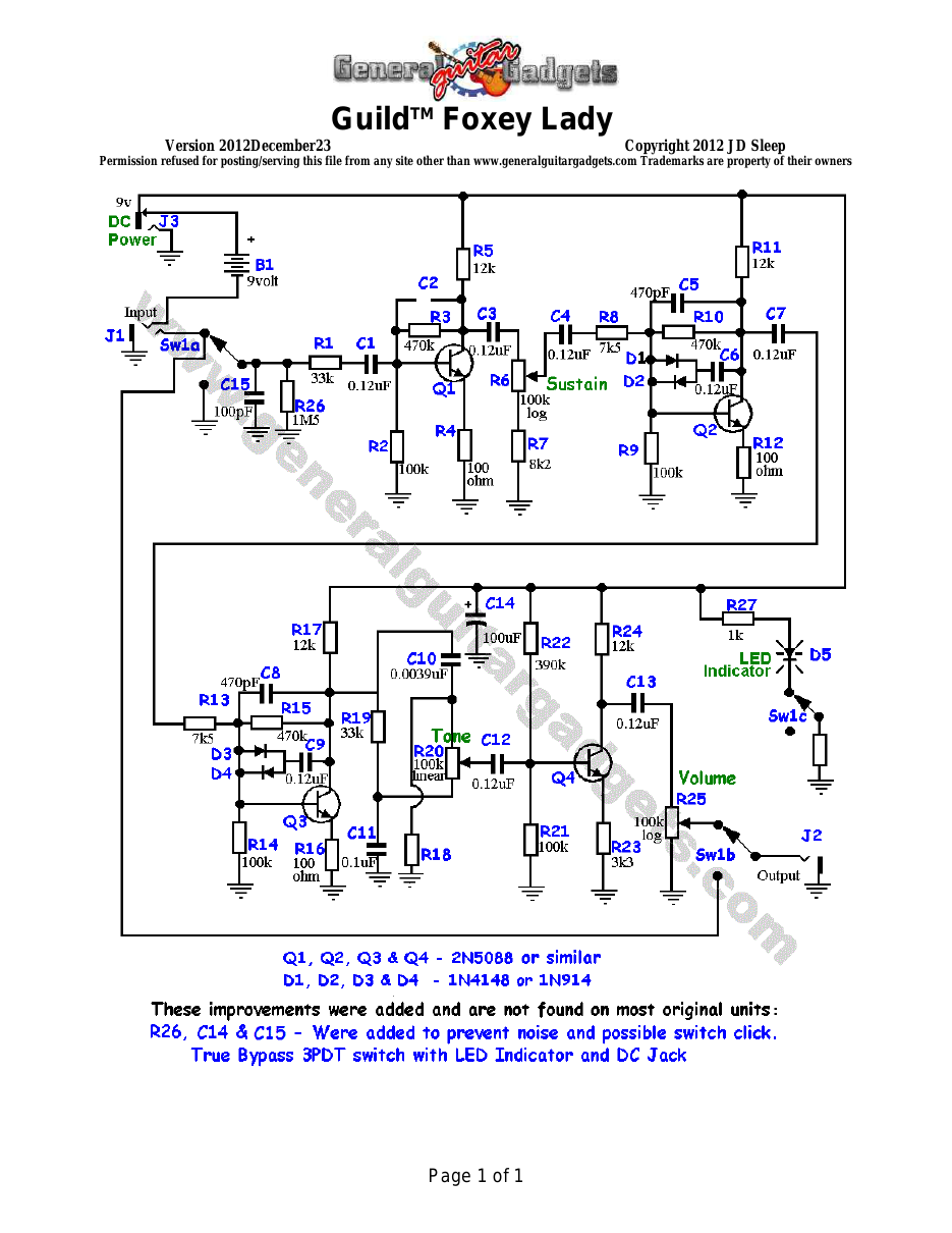
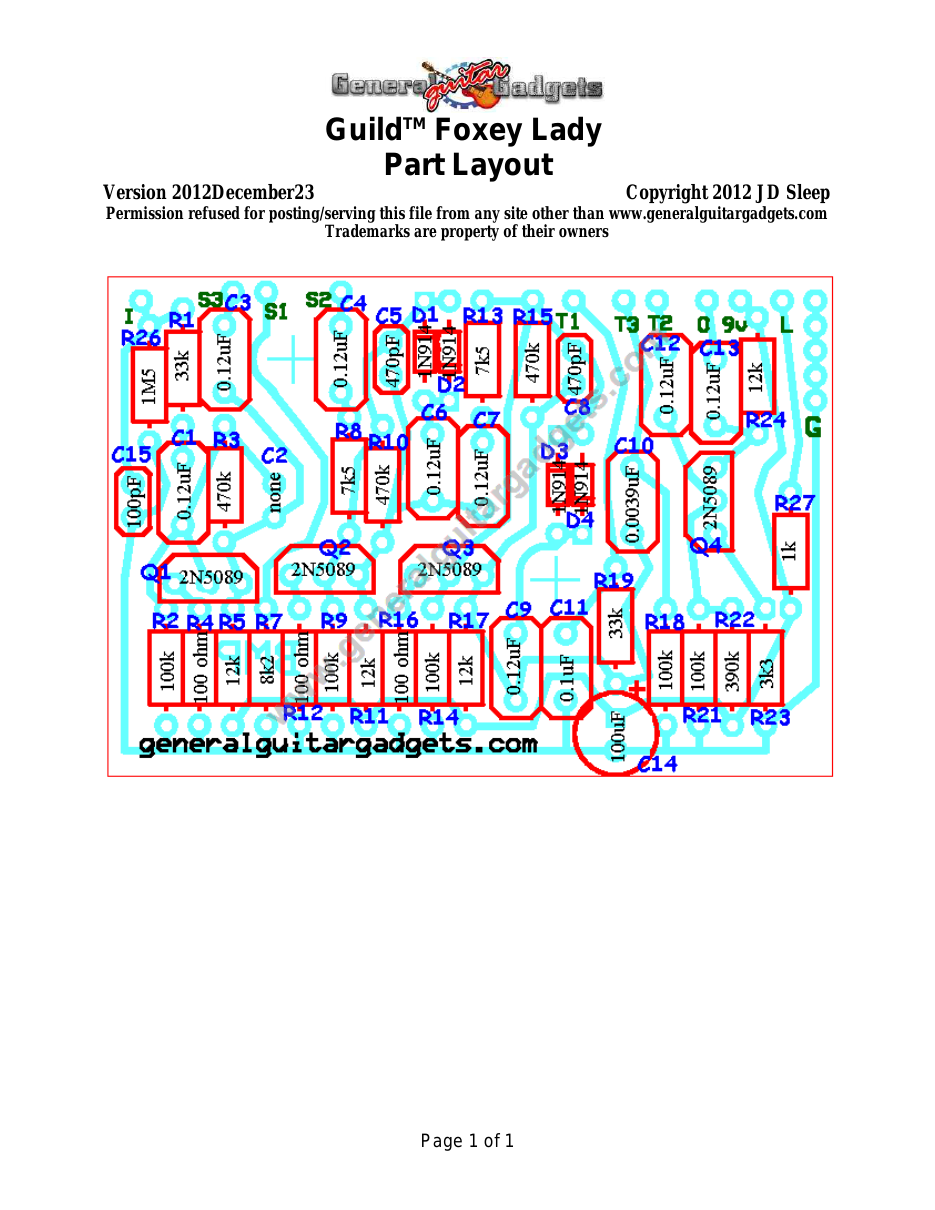
Guild™ Foxey Lady™ Replica known as the GFL. The original stompbox from the 70's was manufactured by Electro Harmonix™ and is in fact a Big Muff Pi™ distortion! The values on the units traced have some part value differences from any of the Big Muff™ versions, so we thought it was worthy of posting in case you love that sound and have to have one! Note that the PCB is the same PCB used in the BMP project and does have the label "BMP" on it. The Wiring Diagram and PCB layout below are "borrowed" from the BMP project.
What you will need
Bill of Materials
Version 2012January30 · Copyright 2007 JD Sleep · Permission refused for posting/serving this file from any site other than www.generalguitargadgets.com · Trademarks are property of their owners
Resistors
| Resistor ID | Value | 3-band Marking | 4-band Marking |
|---|---|---|---|
| R1 | 33k | orange-orange-orange | orange-orange-black-red |
| R2 | 100k | brown-black-yellow | brown-black-black-orange |
| R3 | 470k | yellow-violet-yellow | yellow-violet-black-orange |
| R4 | 100 ohm | brown-black-brown | brown-black-black-black |
| R5 | 12k | brown-red-orange | brown-red-black-red |
| R7 | 8k2 (8.2k) | gray-red-red | gray-red-black-brown |
| R8 | 7k5 (7.5k) | violet-green-red | violet-green-black-brown |
| R9 | 100k | brown-black-yellow | brown-black-black-orange |
| R10 | 470k | yellow-violet-yellow | yellow-violet-black-orange |
| R11 | 12k | brown-red-orange | brown-red-black-red |
| R12 | 100 ohm | brown-black-brown | brown-black-black-black |
| R13 | 7k5 (7.5k) | violet-green-red | violet-green-black-brown |
| R14 | 100k | brown-black-yellow | brown-black-black-orange |
| R15 | 470k | yellow-violet-yellow | yellow-violet-black-orange |
| R16 | 100 ohm | brown-black-brown | brown-black-black-black |
| R17 | 12k | brown-red-orange | brown-red-black-red |
| R18 | 100k | brown-black-yellow | brown-black-black-orange |
| R19 | 33k | orange-orange-orange | orange-orange-black-red |
| R21 | 100k | brown-black-yellow | brown-black-black-orange |
| R22 | 390k | orange-white-yellow | orange-white-black-orange |
| R23 | 3k3 (3.3k) | orange-orange-red | orange-orange-black-brown |
| R24 | 12k | brown-red-orange | brown-red-black-red |
| R26 | 1M5 (1.5M) | brown-green-green | brown-green-black-yellow |
| R27 | 1k | brown-black-red | brown-black-black-brown |
Capacitors
| Capacitor ID | Value | Type | Possible Marking |
|---|---|---|---|
| C1 | 0.1µF | Film | 104 |
| C2 | None | ||
| C3 | 0.12µF | Film | 124 |
| C4 | 0.12µF | Film | 124 |
| C5 | 470pF | Ceramic or Film | 471 |
| C6 | 0.12µF | Film | 124 |
| C7 | 0.12µF | Film | 124 |
| C8 | 470pF | Ceramic or Film | 471 |
| C9 | 0.12µF | Film | 124 |
| C10 | 0.0039µF | Ceramic or Film | 392 or 3n9 |
| C11 | 0.1µF | Film | 104 |
| C12 | 0.12µF | Film | 124 |
| C13 | 0.12µF | Film | 124 |
| C14 | 100µF | Aluminum Electrolytic | 100µF |
| C15 | 100pF | Ceramic or Film | 101 (or100pF) |
Potentiometers
| Part ID | Value | Type |
|---|---|---|
| R6 - Sustain Control | 100k | Log (or Audio) Taper |
| R20 - Tone Control | 100k | Linear Taper |
| R25 - Volume Control | 100k | Log (or Audio) Taper |
Other
| Part ID | Part Name |
|---|---|
| D1 | 1N914 |
| D2 | 1N914 |
| D3 | 1N914 |
| D4 | 1N914 |
| D5 | LED |
| Q1 | NPN bipolar junction transistor |
| Q2 | NPN bipolar junction transistor |
| Q3 | NPN bipolar junction transistor |
| Q4 | NPN bipolar junction transistor |
| J1 | Stereo quarter-inch jack |
| J2 | Mono quarter-inch jack |
| J3 | DC Jack |
| B1 | 9 volt battery (not inlcuded in the Kit) |
| Sw1 Examples of other NPN bipolar junction transistors: ● 2N5088 (original) ● 2N3904 ● 2N4401 ● many others | Heavy Duty 3PDT foot switch 9v battery snap, Printed Circuit Board, 24 gauge stranded wire, Enclosure, Knobs |
How to build it
Instructions
Version 2007September18 · Copyright 2007 JD Sleep · Permission refused for posting/serving this file from any site other than www.generalguitargadgets.com · Trademarks are property of their owners
This is a replica of the GuildTM Foxey LadyTM referred to as GFL in these documents. This pedal was manufactured by Electro Harmonix™ and is in fact another version of the Big Muff Pi™. Use the project documents provided, starting with the General Build Instructions. Refer to the BMP Project for reference if needed. Comments and questions are welcome and can be sent to [email protected] Here is a chart of voltages taken at the transistor pins. This information can be used to help you find and fix problems if your BMP doesn't work when you test it.
Component
Location
9 volt power supply Q1
Q2
Q3
Q4
Voltage
8.8
Collector
3.9
Base
0.6
Emitter
0.03
Collector
3.8
Base
0.6
Emitter
0.03
Collector
3.8
Base
0.6
Emitter
0.03
Collector
4.0
Emitter
2.5
Base
1.8

More about this project
Notes, sounds and related links

Ready to build? We have the kit.
Would you like a Ready to Solder Circuit Board for this project?