
Project · Distortion
DOD™ Overdrive 250
The DOD™ Overdrive 250 distortion pedal is very similar to the MXR™ Distortion Plus™ pedal. This project uses the same Ready-For-Transfer Printed Circuit Board Layout file that is used in the MXR™ Distortion Plus™ Project on this site. This is really a great sounding distortion pedal, remenisent of some of the great sounds of the 1970's. In our option, the 741 IC or similar, is essential to the great sound. Note: Trademarks mentioned here belong to their owners and not to General Guitar Gadgets
Project files
Everything you need to build it
DOD™ Overdrive 250 Ready-For-Transfer Printed Circuit Board Layout
DOD™ Overdrive 250 '77 Ready-For-Transfer Printed Circuit Board Layout For use only if you are a complete DIY person who wants to etch and drill your own PCB. Otherwise, we recommend you ignore this PCB mask and buy the Ready-to-Solder Printed Circuit Board or Complete Kit from the links below.
Schematic
Schematic
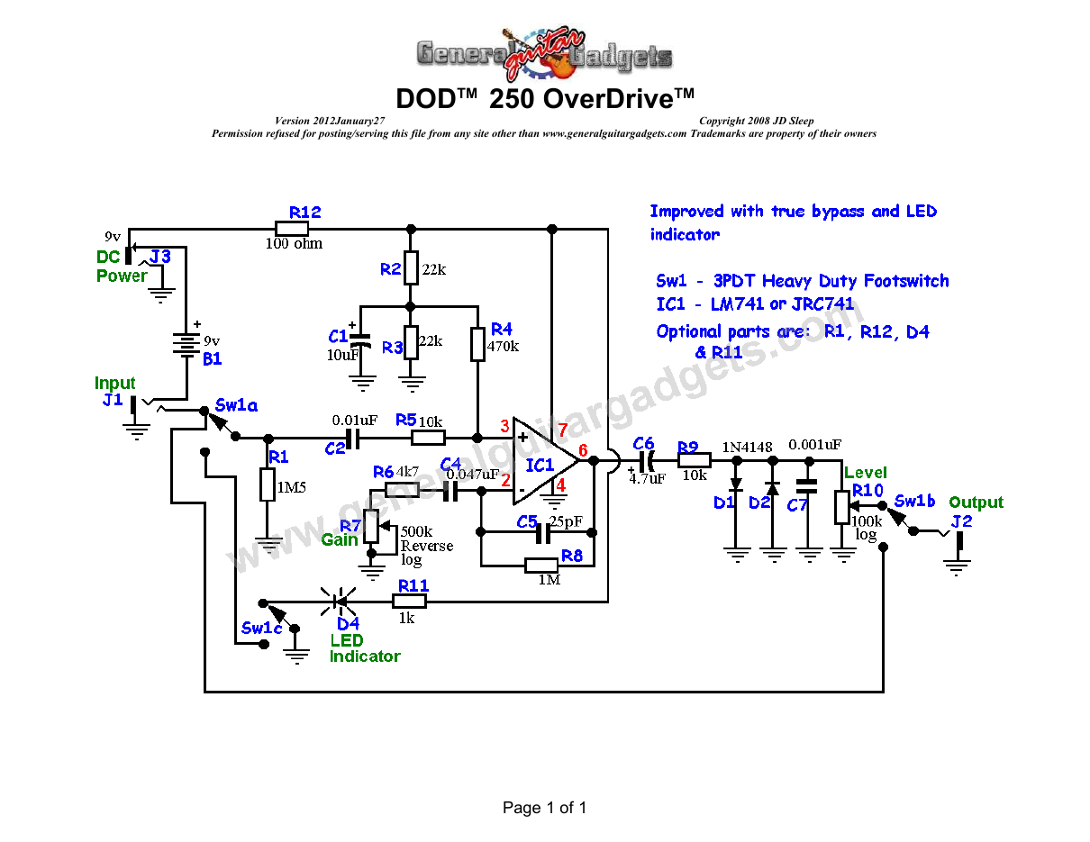
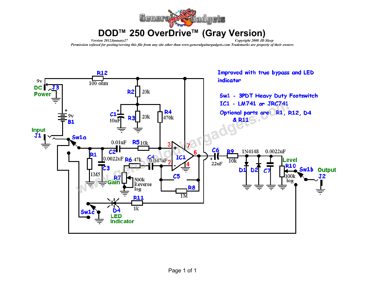
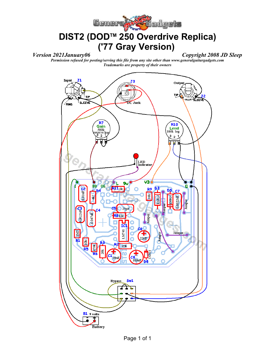
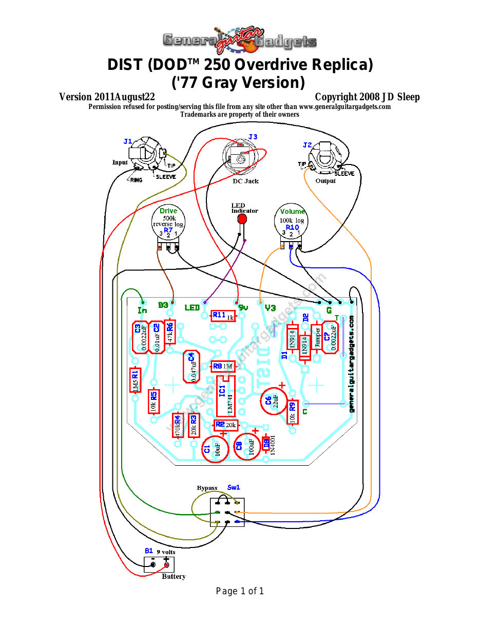
Parts layout
Parts Layout / Wiring Diagram
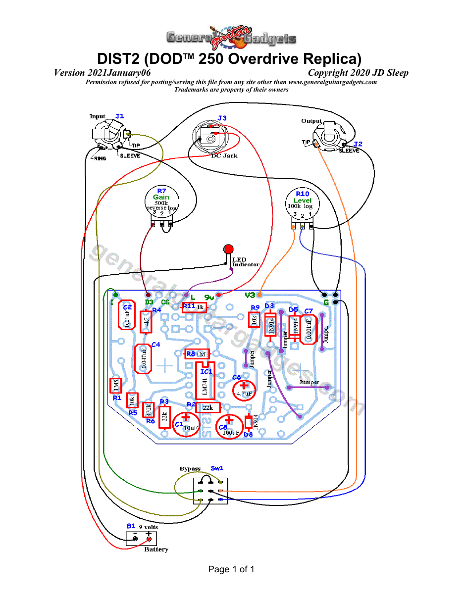
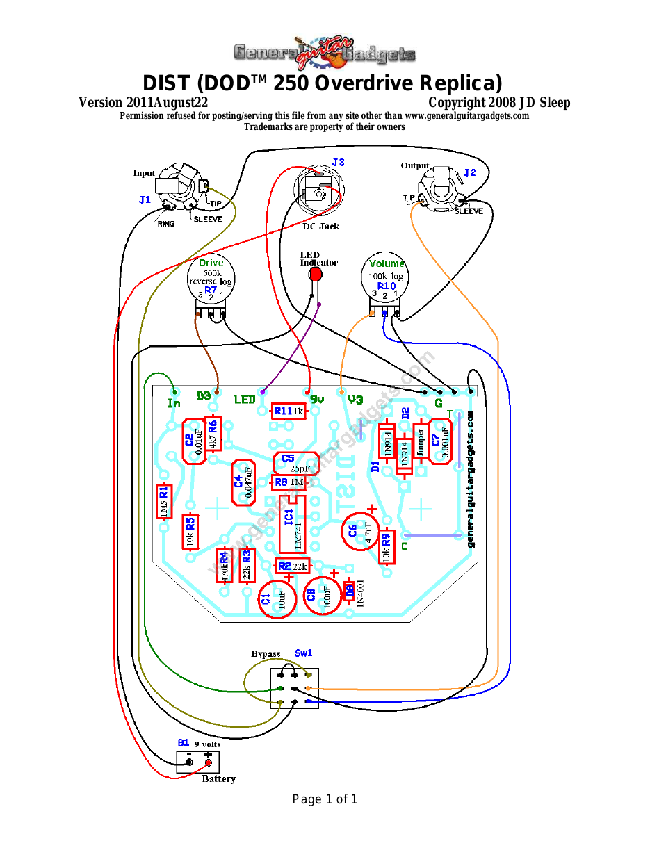
What you will need
Bill of Materials
Version 2012January30 · Copyright 2009 JD Sleep · Permission refused for posting/serving this file from any site other than www.generalguitargadgets.com · Trademarks are property of their owners
Resistors
| Resistor ID | Value | 3-band Marking | 4-band Marking |
|---|---|---|---|
| R1 | 1M5 | brown-green-green | brown-green-black-yellow |
| R2 | 22k | red-red-orange | red-red-black-red |
| R3 | 22k | red-red-orange | red-red-black-red |
| R4 | 470k | yellow-violet-yellow | yellow-violet-black-orange |
| R5 | 10k | brown-black-orange | brown-black-black-red |
| R6 | 4k7 (4.7k) | yellow-violet-red | yellow-violet-black-brown |
| R6 (optional value) | 47k (this is an optional value, see instructions for details) | yellow-violet-orange | yellow-violet-black-red |
| R7 | 500k Reverse Log Potentiometer | ||
| R8 | 1M | brown-black-green | brown-black-black-yellow |
| R9 | 10k | brown-black-orange | brown-black-black-red |
| R10 | 100k Log Potentiometer | ||
| R11 | 1k | brown-black-red | brown-black-black-brown |
| R12 (optional) | 100 ohm | brown-black-brown | brown-black-black-black |
Capacitors
| Capacitor ID | Value | Type | Possible Marking |
|---|---|---|---|
| C1 | 10µF | Tantalum or Aluminum Electrolytic | 10uF |
| C2 | 0.01µF | Film | 103 |
| C3 | none | ||
| C4 | 0.047µF | Film | 473 |
| C5 | 25pF | ceramic | 25 |
| C6 | 4.7µF | Tantalum or Aluminum Electrolytic | 4.7µF |
| C7 | 0.001µF | Film or Ceramic | 102 or 1n |
| C8 (optional) | 100µF | Aluminum Electrolytic | 100µF |
Potentiometers
| Part ID | Value | Type |
|---|---|---|
| R7 - Gain | 500k | Reverse Log Taper Potentiometer |
| R10 - Volume | 100k | Log (Audio) Taper Potentiometer |
Other
| Part ID | Part Name |
|---|---|
| IC1 | JRC741 Opamp |
| D1 | 1N914 or other clipping device |
| D2 | 1N914 or other clipping device |
| D4 | Status Indicator LED and holder |
| D8 (optional) | 1N4001 or 1N914 |
| J1 | Stereo quarter-inch jack |
| J2 | Mono quarter-inch jack |
| J3 | DC Jack |
| B1 | 9 volt battery (not included in the Kit) |
| Sw1 | Heavy Duty 3PDT foot switch 9v battery snap, Printed Circuit Board 24 gauge stranded wire, Enclosure, Knobs |
How to build it
Instructions
DOD™ Overdrive 250 Replica Build Instructions
Version 2021October03 · Copyright 2014, 2021 JD Sleep · Permission refused for posting/serving this file from any site other than www.generalguitargadgets.com · Trademarks are property of their owners
This is the Build Instructions for: a replica of any of these: MXR™ Distortion Plus™ DOD™ 250 Overdrive DOD™ 250 Overdrive ('77 Gray Version) Ross™ Distortion The Kit is referred to as DIST in these documents. These distortion units are very similar, differing in only a few part values, circuits being almost identical. For that reason, we have the same circuit board and we have one set of instructions that apply to all units. The Ross™ Distortion should be mentioned here as well, since it is an almost identical circuit, but uses half of a dual IC instead of the 741 IC.
About the Part Values
There have been variations on part values for both the Distortion Plus™ and the 250 Overdrive over the years, and both have been discontinued at one point and reissued after several years of absence on the new pedal market. When we speak of the "741" IC in this project we are referring to an of the manufactured versions: UA741, LM741 or JRC741 with various suffix letters possibly tagging on to the part number. The Ross™ Distortion originally used a dual opamp. Also some of the reissues use dual opamps. If you are looking for an absolute part-for-part replica of the Ross™, you'll have to look elsewhere since the layout of the PCB is for a single opamp, not a dual. We believe that the 741 will sound wonderful even in the Ross™. All Units ● We cannot over-emphasize the importance of using the "741" IC for this unit. There are lots of pin-compatible single-opamps available with much better quality and better specs. It may be tempting to use something else, but this distortion "plays" off the specs of the 741 to some extent. It is highly recommended to stick with the 741. ● The diodes vary from unit to unit. See the Bill of Materials for the unit you are building. The Ross™ Distortion used germanium diodes with very good results. Also, red LEDs have an excellent sound in this distortion (Kits do not contail
●
red LEDs though). There are three jumpers that are built in to the top layer of the PCB. They are sort of violet color on the layout/wiring diagrams. If you are using one of our PCB, you do not need to install jumpers there.
The Distortion Plus™
The Volume Control potentiometer has been traced as 10k log or 50k log on some versions, The reissue has a 100k log potentiometer. For best results in output volume, use the 100k log potentiometer. It won't change the sound characteristics, but will give a better output volume control. The 250 Overdrive This project covers two of the versions, an early version in a gray painted box and the later yellow box version, Here's some notes on some part value variations. ● Some versions had R12 (100 ohm resistor) and some didn't. If you use strictly battery power, you probably don't need it. If you want to include it, it will have to be solder tacked on to the DC jack or off the PCB power pad. ● Some versions have C5 of 25pF and some versions don't have it. If you don't use it, just omit it and don't use a jumper. If you use a 741 IC, you probably won't need it. For other pin-compatible ICs that you might use, it may be useful to smooth down the high end. ● Some schematics on the web list R6 in the DOD™ 250 Overdrive as a 47k resistor. The gray version had a 47k value. The 47k value should raise the minimum level of overdrive to some extent, which is probably not a bad thing since the minimum level with a 4k7 is very weak. Consider using the 47k value for R6 for any version you build.
Building
●
●
Use the project documents provided, starting with the General Build Instructions. Follow the layout diagrams to add components to the PCB and the wiring diagrams to hook it all up. There are photos in this document to give some ideas of the overall layout and wiring. Note that there are two jumpers on the diagrams, if you look at the PCB that comes with the kit, you can see that these jumpers are already on the top layer of the PCB, there is no need to install a jumper in those positions. There is a
●
jumper included in the kits that can be used for D3 if you don't do asymmetrical clipping arrangement. There is lots of room on the PCB for mods. Extra clippers can be put in the feedback loop in D4 through D7. This will give more distortion as you would expect. D1 and D2 have extra holes so that you could add extra diodes there (standing on end) for a more "over drivey" sound. C9 is normally not used and is jumpered, but if you added a tone control you can cut the jumper and add an output capacitor there.
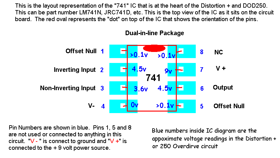
Comments and questions are welcome and can be sent to [email protected] Here is a chart of voltages taken at the IC pins. This information can be used to help you find and fix problems if your DIST doesn't work when you test it.
DOD™ Overdrive 250 '77 Gray Version Replica Build Instructions
Version 2021October03 · Copyright 2014, 2021 JD Sleep · Permission refused for posting/serving this file from any site other than www.generalguitargadgets.com · Trademarks are property of their owners
This is the Build Instructions for: a replica of any of these: MXR™ Distortion Plus™ DOD™ 250 Overdrive DOD™ 250 Overdrive ('77 Gray Version) Ross™ Distortion The Kit is referred to as DIST in these documents. These distortion units are very similar, differing in only a few part values, circuits being almost identical. For that reason, we have the same circuit board and we have one set of instructions that apply to all units. The Ross™ Distortion should be mentioned here as well, since it is an almost identical circuit, but uses half of a dual IC instead of the 741 IC.
About the Part Values
There have been variations on part values for both the Distortion Plus™ and the 250 Overdrive over the years, and both have been discontinued at one point and reissued after several years of absence on the new pedal market. When we speak of the "741" IC in this project we are referring to an of the manufactured versions: UA741, LM741 or JRC741 with various suffix letters possibly tagging on to the part number. The Ross™ Distortion originally used a dual opamp. Also some of the reissues use dual opamps. If you are looking for an absolute part-for-part replica of the Ross™, you'll have to look elsewhere since the layout of the PCB is for a single opamp, not a dual. We believe that the 741 will sound wonderful even in the Ross™. All Units ● We cannot over-emphasize the importance of using the "741" IC for this unit. There are lots of pin-compatible single-opamps available with much better quality and better specs. It may be tempting to use something else, but this distortion "plays" off the specs of the 741 to some extent. It is highly recommended to stick with the 741. ● The diodes vary from unit to unit. See the Bill of Materials for the unit you are building. The Ross™ Distortion used germanium diodes with very good results. Also, red LEDs have an excellent sound in this distortion (Kits do not contail
●
red LEDs though). There are three jumpers that are built in to the top layer of the PCB. They are sort of violet color on the layout/wiring diagrams. If you are using one of our PCB, you do not need to install jumpers there.
The Distortion Plus™
The Volume Control potentiometer has been traced as 10k log or 50k log on some versions, The reissue has a 100k log potentiometer. For best results in output volume, use the 100k log potentiometer. It won't change the sound characteristics, but will give a better output volume control. The 250 Overdrive This project covers two of the versions, an early version in a gray painted box and the later yellow box version, Here's some notes on some part value variations. ● Some versions had R12 (100 ohm resistor) and some didn't. If you use strictly battery power, you probably don't need it. If you want to include it, it will have to be solder tacked on to the DC jack or off the PCB power pad. ● Some versions have C5 of 25pF and some versions don't have it. If you don't use it, just omit it and don't use a jumper. If you use a 741 IC, you probably won't need it. For other pin-compatible ICs that you might use, it may be useful to smooth down the high end. ● Some schematics on the web list R6 in the DOD™ 250 Overdrive as a 47k resistor. The gray version had a 47k value. The 47k value should raise the minimum level of overdrive to some extent, which is probably not a bad thing since the minimum level with a 4k7 is very weak. Consider using the 47k value for R6 for any version you build.
Building
●
●
Use the project documents provided, starting with the General Build Instructions. Follow the layout diagrams to add components to the PCB and the wiring diagrams to hook it all up. There are photos in this document to give some ideas of the overall layout and wiring. Note that there are two jumpers on the diagrams, if you look at the PCB that comes with the kit, you can see that these jumpers are already on the top layer of the PCB, there is no need to install a jumper in those positions. There is a
●
jumper included in the kits that can be used for D3 if you don't do asymmetrical clipping arrangement. There is lots of room on the PCB for mods. Extra clippers can be put in the feedback loop in D4 through D7. This will give more distortion as you would expect. D1 and D2 have extra holes so that you could add extra diodes there (standing on end) for a more "over drivey" sound. C9 is normally not used and is jumpered, but if you added a tone control you can cut the jumper and add an output capacitor there.
Comments and questions are welcome and can be sent to [email protected] Here is a chart of voltages taken at the IC pins. This information can be used to help you find and fix problems if your DIST doesn't work when you test it.
More about this project
Notes, sounds and related links
To Build a '77 Gray version, use these diagrams:


The following distortions can be built with the DIST Complete Kit or the Ready-to-Solder Printed Circuit Board. The Kit includes all parts for a replica of any of these distortion pedals!
- MXR™ Distortion Plus™
- DOD™ 250 Overdrive
- '77 Gray DOD™ 250 Overdrive
- Ross™ Distortion
Ready to build? We have the kit.
Buy a DIST Complete Kit. Includes all the parts and materials you need to build one, all for about the price you would pay for a PCB and parts.
Would you like a Ready to Solder Circuit Board for this project? Note: If you buy the kit, the Ready-to-Solder Circuit Board (RTS PCB) is included in the kit. You do not need to purchase this RTS PCB if you buy the kit.