
Project · Distortion
BSIAB 2
Brown Sound In A Box version 2 (BSIAB2) is an excellent distortion pedal designed by Ed Guidry. Based on the AMZ MiniBooster cascading work done by Jack Orman and further refined by Aron Nelson and Doug Hammond.
This is one of the best heavy Marshall™-type distortion boxes that we've heard and it also performs very well on low drive as you can hear at the beginning of the sound sample below.
The story
About the circuit
"Brown sound" is the DIY community's name for the tone of a cranked early-'70s Marshall™: Eddie Van Halen's first albums, in particular. Brown Sound In A Box was designed by Ed Guidry in 2001 on the DIY stompbox forums as an all-JFET answer to that tone. Rather than clipping with diodes, it cascades several JFET gain stages, each one driving the next into overdrive the way tube stages do in an amp. It grew out of Jack Orman's AMZ Mini-Booster, and the second version, refined on the forums by Aron Nelson and Doug Hammond, is the one that stuck. It has become one of the most-built DIY distortions of all time, and it does low-gain crunch as well as it does full saturation.
This project at GGG
JD had the original BSIAB on this site within months of Ed Guidry posting it, and when the forums settled on the improved second version we followed with the BSIAB2. Our layout has been the reference board for it for most of the circuit's life. It is a good example of how the DIY community works: a circuit posted on a forum, improved by the people who built it, and documented here so anyone can build it. The build uses five 2N5457 JFETs (J201s also work in two positions) with a trimmer to set the last stage's drain voltage; JFETs vary, so the instructions include a chart of the voltages we measured on a good-sounding unit to help you dial yours in. The modification notes add a bass-boost tweak and an optional Contour control, with its own wiring diagram.
Project files
Everything you need to build it
BSIAB2 Ready-For-Transfer Printed Circuit Board Layout For use only if you are a complete DIY person who wants to etch and drill your own PCB. Otherwise, we recommend you ignore this PCB mask and buy the Ready-to-Solder Printed Circuit Board or Complete Kit from the links below.
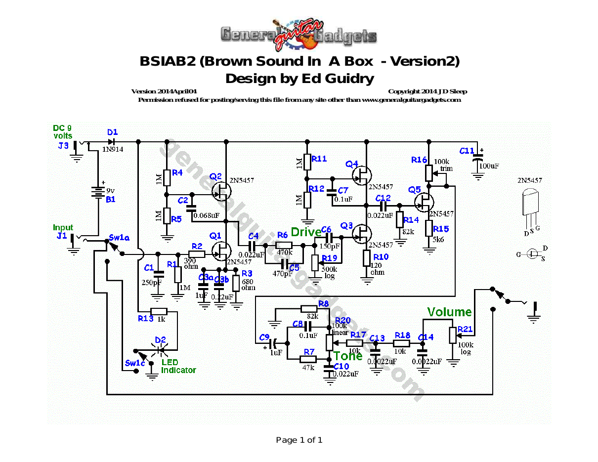
Parts layout
Parts Layout / Wiring Diagram
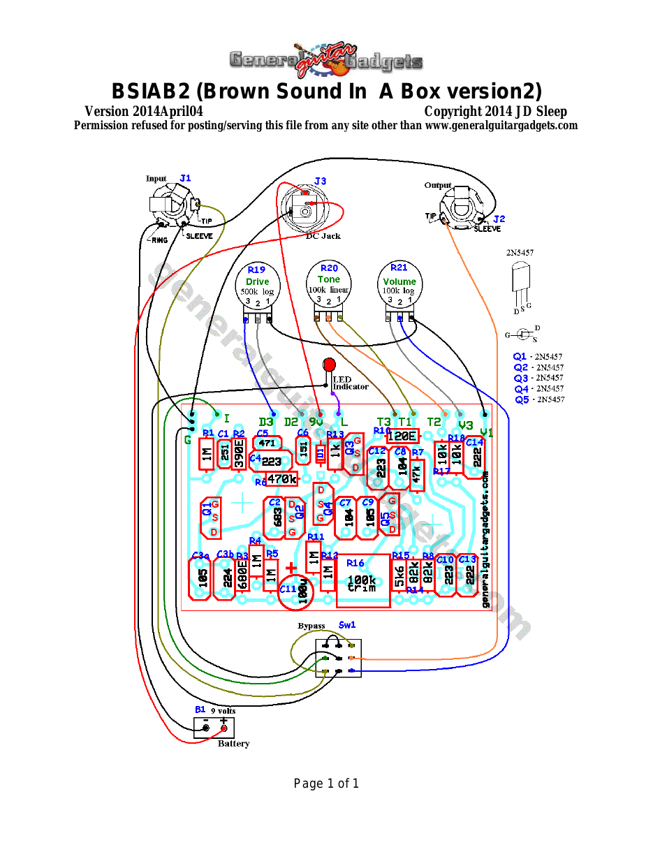
What you will need
Bill of Materials
Version 2014April04 · Copyright 2014 JD Sleep · Permission refused for posting/serving this file from any site other than www.generalguitargadgets.com · Trademarks are property of their owners
Resistors
| Resistor ID | Value | 3-band Marking | 4-band Marking |
|---|---|---|---|
| R1 | 1M | brown-black-green | brown-black-black-yellow |
| R2 | 390 ohm | orange-white-brown | orange-white-black-black |
| R3 | 680 ohm | blue-gray-brown | blue-gray-black-black |
| R4 | 1M | brown-black-green | brown-black-black-yellow |
| R5 | 1M | brown-black-green | brown-black-black-yellow |
| R6 | 470k | yellow-violet-yellow | yellow-violet-black-orange |
| R7 | 47k | yellow-violet-orange | yellow-violet-black-red |
| R8 | 82k | gray-red-orange | gray-red-black-red |
| R9 | none | ||
| R10 | 120 ohm | brown-red-brown | brown-red-black-black |
| R11 | 1M | brown-black-green | brown-black-black-yellow |
| R12 | 1M | brown-black-green | brown-black-black-yellow |
| R13 | 1k | brown-black-red | brown-black-black-brown |
| R14 | 82k | gray-red-orange | gray-red-black-red |
| R15 | 5k6 (5.6k) | green-blue-red | green-blue-black-brown |
| R17 | 10k | brown-black-orange | brown-black-black-red |
| R18 | 10k | brown-black-orange | brown-black-black-red |
Capacitors
| Capacitor ID | Value | Type | Possible Marking |
|---|---|---|---|
| C1 | 250pF | Ceramic | 251 |
| C2 | 0.068uF | Film | 683 |
| C3a | 1uF | Film | 105 |
| C3b | 0.22uF | Film | 224 |
| C4 | 0.022uF | Film | 223 |
| C5 | 470pF | Silver Mica (or Polystyrene) | 471 or 470 |
| C6 | 150pF | Ceramic | 151 or 150 |
| C7 | 0.1uF | Film | 104 |
| C8 | 0.1uF | Film | 104 |
| C9 | 1uF | Film | 105 |
| C10 | 0.022uF | Film | 223 |
| C11 | 100uF | Aluminum Electrolytic | 100uF |
| C12 | 0.022uF | Film | 223 |
| C13 | 0.0022uF | Film | 222 or 2n2 |
| C14 Potentiometers | 0.0022uF Part Id | Film | 222 or 2n2 Value |
| R19 (Drive) | 500k log | ||
| R20 (Tone) | 100k linear | ||
| R21 (Volume) | 100k log | ||
| R16 | 100k Trimmer |
Other
| Part ID | Part Name |
|---|---|
| D1 | 1N914 |
| Q1 | 2N5457 |
| Q2 | 2N5457 |
| Q3 | 2N5457 (or J201) |
| Q4 | 2N5457 (or J201) |
| Q5 | 2N5457 |
| J1 | Stereo quarter-inch jack |
| J2 | Mono quarter-inch jack |
| J3 | DC Jack |
| B1 | 9 volt battery (not included in the Kit) |
| Sw1 | Heavy Duty 3PDT footswitch (bypass) 9v battery snap, Printed Circuit Board, 24 gauge stranded wire, knobs enclosure |
How to build it
Instructions
Version 2010February17 · Copyright 2006 JD Sleep · Permission refused for posting/serving this file from any site other than www.generalguitargadgets.com · Trademarks are property of their owners
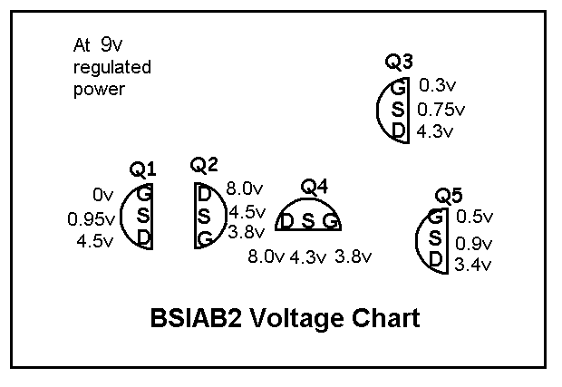
This distortion is meant to make a clean set amp sound like a cranked Marshall™ amp. Of course there are some limitations, but it does a very good job in our opinion. Use the project documents provided, starting with the General Build Instructions. JFET transistors can be inconsistent in sound and operation. If you have problems getting a full sound or if the voltages don't seem quite right, try a new JFET transistor of the same type and see if there is any improvement. The trimmer adjustment is used to set the Drain voltage of Q5 at about half the power voltage. Note that the protection diode cuts the voltage of the power rail down by about a volt, so the Drain voltage should be about 4 volts with a nine volt battery. It's best to fine tune this by ear. The higher the Drain voltage, the higher the noise level, if it gets too low, it starts to sputter and doesn't perform well.
Here is a chart of voltages taken at the transistor pins. This information can be used to help you find and fix problems if your BSIAB2 doesn't work when you test it. Note that Q5 has a Drain voltage set at 3.4 volts by the trimmer setting. This particular unit sounded good at that setting, if you tune yours to closer to 4 volts, the Gate and Source voltages may vary some. Your unit may have some variation in voltage readings compared with the diagram. They don't have to be exactly as the chart, but you should be somewhere in the general range.
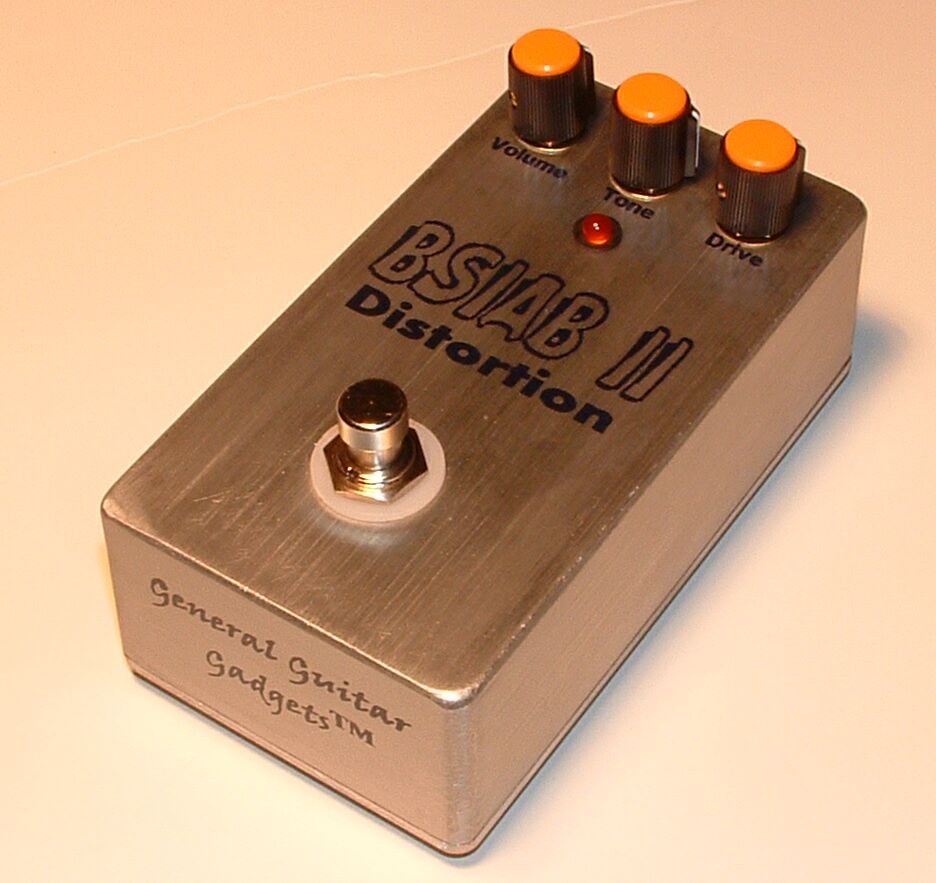
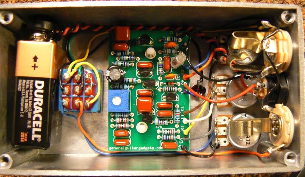
Here's a photo of the inside of a BSIAB2:
Make it your own
Modification Instructions
Version 2011November09 · Copyright 2011 JD Sleep · Permission refused for posting/serving this file from any site other than www.generalguitargadgets.com · Trademarks are property of their owners
More Bass in Tone
1. Completely Remove R8 from the PCB. This changes the “Tone Stack” to give more bass response. Do not jumper R8 just completely remove it from the circuit. 2. Solder tack a 0.22uF film capacitor across R15. So, you end up with a 0.22uF capacitor parallel to the R15 resistor.
More Control on the Tone
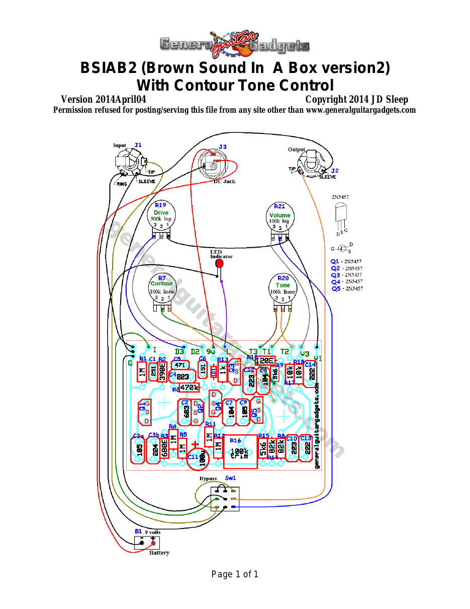
Add a “Contour” control to the Tone Stack. The wiring diagram is listed on the project page. Replace R7 with a 5k6 resistor and a 100k potentiometer as shown in the wiring diagram for this mod.
Want to contribute? If you are happy to share your modification information with other builders, contact us at [email protected]. If the modifications pass our review we will add it to this file for all to enjoy!

More about this project
Notes, sounds and related links
Here is a diagram for the modification of adding a "Contour" control. This mod, you replace R7 with a 5k6 resistor and a 100k pot. This allows you to dial in some more tone variations.

Ready to build? We have the kit.
Buy a BSIAB2 Complete Kit. Includes all the parts and materials you need to build one, all for about the price you would pay for a PCB and parts.

Would you like a Ready to Solder Circuit Board for this project? Note: If you buy the kit, the Ready-to-Solder Circuit Board (RTS PCB) is included in the kit. You do not need to purchase this RTS PCB if you buy the kit.