
Project · Distortion
Boss™ SD-1™ Replica
This is a replica of the Boss™ SD-1™ Distortion. This replica does not include the FET switching circuit of the original, it uses a true (total) bypass switch with an LED indicator circuit. The switching circuit has no effect on the sound of the stompbox. Trademarks used here belong to their owners and no General Guitar Gadgets
Project files
Everything you need to build it
ITS8 Ready-For-Transfer Printed Circuit Board Layout - For use only if you are a complete DIY person who wants to etch and drill your own PCB. Otherwise, we recommend you ignore this PCB mask and buy the Ready-to-Solder Printed Circuit Board or Complete Kit from the links below.
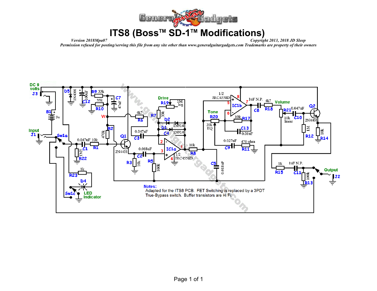
Parts layout
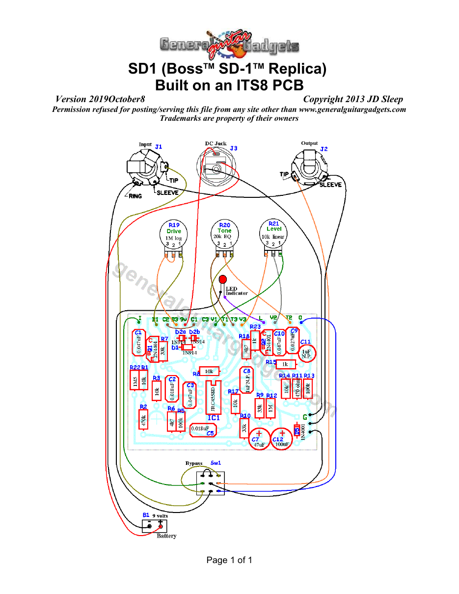
Parts Layout / Wiring Diagram
What you will need
Bill of Materials
Version 2018May07 · Copyright 2018 JD Sleep · Permission refused for posting/serving this file from any site other than www.generalguitargadgets.com · Trademarks are property of their owners
Resistors
| Resistor ID | Value | 3-band Marking | 4-band Marking |
|---|---|---|---|
| R1 | 1k | brown-black-red | brown-black-black-brown |
| R2 | 470k | yellow-violet-yellow | yellow-violet-black-orange |
| R3 | 10k | brown-black-orange | brown-black-black-red |
| R4 | None | ||
| R5 | 100k | brown-black-yellow | brown-black-black-orange |
| R6 | 4k7 (4.7k) | yellow-violet-red | yellow-violet-black-brown |
| R7 | 33k | orange-orange-orange | orange-orange-black-red |
| R8 | 10k | brown-black-orange | brown-black-black-red |
| R9 | 33k | orange-orange-orange | orange-orange-black-red |
| R10 | 33k | orange-orange-orange | orange-orange-black-red |
| R11 | 470 ohm | yellow-violet-brown | yellow-violet-black-black |
| R12 | 1M | brown-black-green | brown-black-black-yellow |
| R13 | 100k | brown-black-yellow | brown-black-black-orange |
| R14 | 10k | brown-black-orange | brown-black-black-red |
| R15 | 1k | brown-black-red | brown-black-black-brown |
| R16 | None | ||
| R17 | 10k | brown-black-orange | brown-black-black-red |
| R18 | 4k7 (4.7k) | yellow-violet-red | yellow-violet-black-brown |
| R22 | 1M5 (1.5M) | brown-green-green | brown-green-black-yellow |
| R23 | 1k | brown-black-red | brown-black-black-brown |
Capacitors
| Capacitor ID | Value | Type | Possible Marking |
|---|---|---|---|
| C1 | 0.047µF | Film | 473 |
| C2 | 0.018µF | Film | 182 |
| C3 | 0.047µF | Film | 473 |
| C4 | None | ||
| C5 | 0.018µF | Film | 183 |
| C6 | None | ||
| C7 | 47µF | Aluminum Electrolytic | 47uF |
| C8 | 1µF | Film | 105 |
| C9 | 0.027µF | Film | 273 |
| C10 | 0.047µF | Film | 473 |
| C11 | 1µF | Film | 105 |
| C12 | 100µF | Aluminum Electrolytic | 100uF |
Potentiometers
| Part ID | Value | Type |
|---|---|---|
| R19 - Drive Control | 1M | Log (or Audio) Taper |
| R20 – Tone Control | 20k | EQ Taper (W) |
| R21 - Level Control | 10k | Linear Taper |
Other
| Part ID | Part Name |
|---|---|
| IC1 | JRC4558D or other dual opamp |
| D1 | 1N914 |
| D2 | 1N914 |
| D2b | 1N914 |
| D3 | None |
| D4 | None |
| D5 | 1N914 or 1N4001 |
| Q1 | NPN bipolar junction transistor |
| Q2 | NPN bipolar junction transistor |
| J1 | Stereo quarter-inch jack |
| J2 | Mono quarter-inch jack |
| J3 | DC Jack |
| B1 | 9 volt battery (not included in the Kit) |
| Sw1 Examples of other NPN bipolar junction transistors: ● 2SC1815 (original) – Has a different Pin format than the PCB uses ● 2N3904 ● 2N4401 ● 2N5088 ● MPSA18 ● many others | Heavy Duty 3PDT foot switch 9v battery snap, Printed Circuit Board, 24 gauge stranded wire, Enclosure, Knobs |
How to build it
Instructions
Version 2018May07 · Copyright 2018 JD Sleep · Permission refused for posting/serving this file from any site other than www.generalguitargadgets.com · Trademarks are property of their owners
This is the Boss™ SD-1™ Distortion Replica. Use the project documents provided, starting with the General Build Instructions. This uses the PCB originally designed for the Ibanez™ TS-808™ replica, but the circuit is similar so it works well here. There are also two wire jumpers that need to be installed across some of the wiring pads as shown in the parts placement/wiring diagram. D5 is optional, it is there to prevent reverse polarity power from destroying the IC. If you decide not to install D5, do not put a jumper in place of D5, just leave it blank. C12 is a power supply filter cap and is also somewhat optional. If you plan on only using battery power, you probably don't need C12. Again, if you don't install C12, do not install a jumper, leave it blank. If you have D5 installed and you do ever zap the unit with reverse power, hopefully all you have to do to fix it is replace or remove D5.
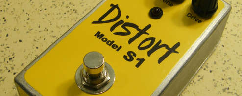
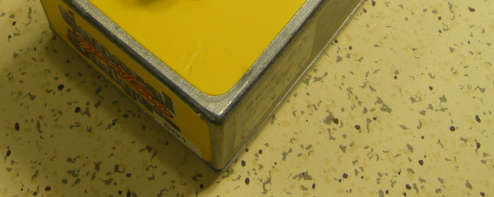
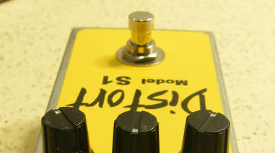
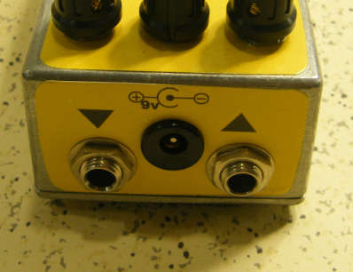
Here's an inside view of the unit we built to show our construction details.
Here is a chart of voltages taken at the IC and transistor pins. This information can be used to help you find and fix problems if your SD-1™ Replica doesn't work when you test it. The voltages are approximate, you may not get these exact readings, but they should be somewhere close.
Component
Location
9 volt power supply IC
Voltage
9.4v
IC Pin 1
4.7v
IC Pin 2
4.8v
IC Pin 3
4.7v
IC Pin 4
0v
IC Pin 5
4.7v




Q1
Q2
IC Pin 6
4.7v
IC Pin 7
4.7v
IC Pin 8
9.4v
Collector
9.4v
Base
4.2v
Emitter
3.9v
Collector
9.4v
Base
4.2v
Emitter
3.9v
Comments and questions are welcome and can be sent to [email protected]
Ready to build? We have the kit.
Would you like a Ready to Solder Circuit Board for this project?
Note: If you buy the kit, the Ready-to-Solder Printed Circuit Board (RTS PCB) is included in the kit. You do not need to purchase this Ready to Solder Circuit Printed Board if you buy the kit.
