
Project · Boosters & Volume
Dan Armstrong™ Red Ranger™ Tone Booster
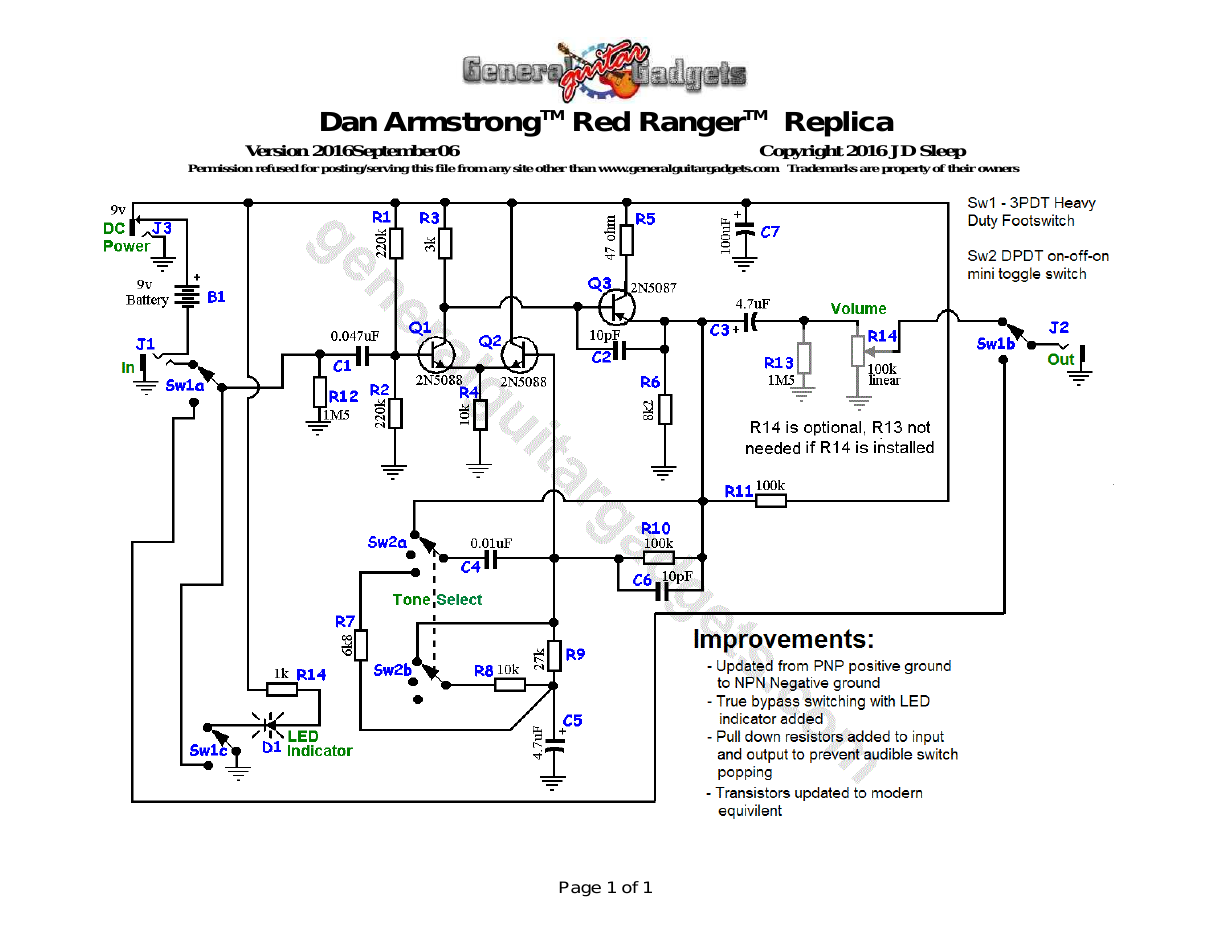
Great boost, with 3 tone boost settings, all 3 setting are useful to most guitar tones. This is the original circuit from the 1970's. It has been updated with negative ground circuit, stompbox format with true-bypass and LED indicator and power supply jack. Note: Trade Marks mentioned here belong to their rightful owners, not General Guitar Gadgets.
Project files
Everything you need to build it
Dan Armstrong™ Red Ranger™ Booster Ready-For-Transfer Printed Circuit Board Layout – For use only if you are a complete DIY person who wants to etch and drill your own PCB. Otherwise, we recommend you ignore this PCB mask and buy the Ready-to-Solder Printed Circuit Board or Complete Kit.
Dan Armstrong™ Red Ranger™ Booster Project Revisions History
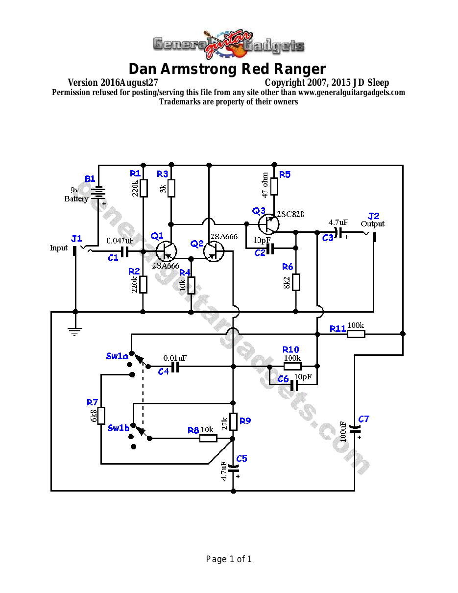
Schematic
Schematic
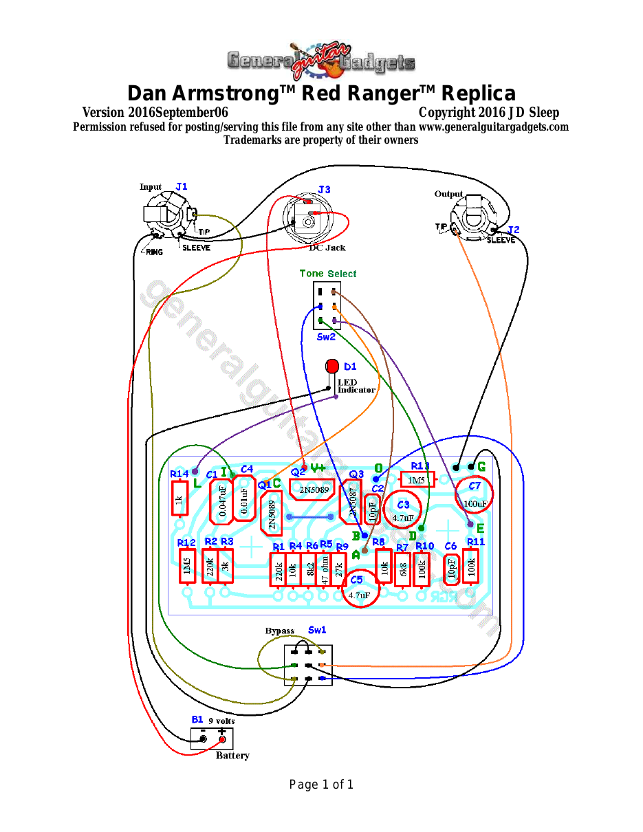
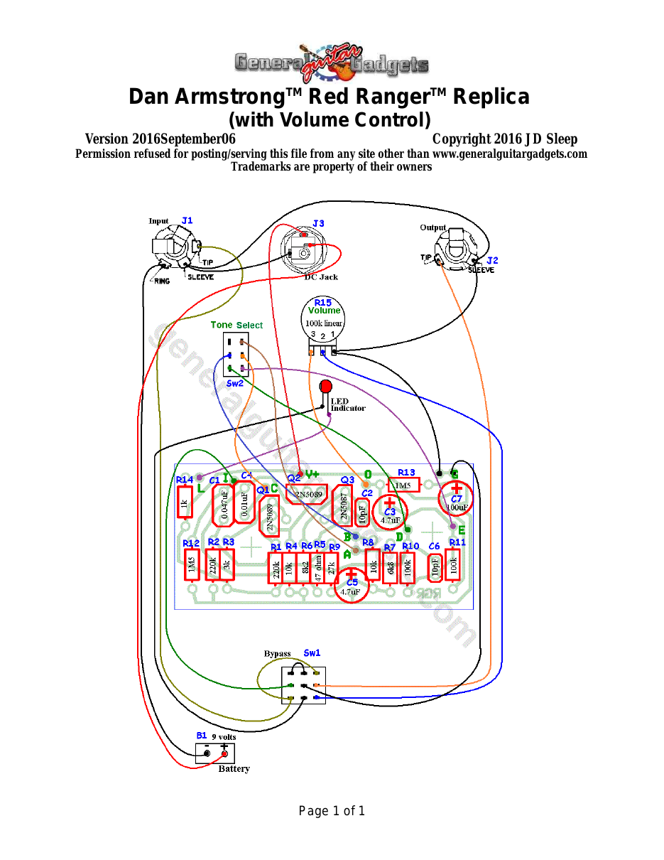
Parts layout
Parts Layout / Wiring Diagram
What you will need
Bill of Materials
Version 2015July19 · Copyright 2015 JD Sleep · Permission refused for posting/serving this file from any site other than www.generalguitargadgets.com · Trademarks are property of their owners
Resistors
| Resistor ID | Value | 3-band Marking | 4-band Marking |
|---|---|---|---|
| R1 | 220k | red-red-yellow | red-red-black-orange |
| R2 | 220k | red-red-yellow | red-red-black-orange |
| R3 | 3k | orange-black-red | orange-black-black-brown |
| R4 | 10k | brown-black-orange | brown-black-black-red |
| R5 | 47 ohm | yellow-violet-black | yellow-violet-black-gold |
| R6 | 8k2 (8.2k) | gray-red-red | gray-red-black-brown |
| R7 | 6k8 (6.8k) | blue-gray-red | blue-gray-black-brown |
| R8 | 10k | brown-black-orange | brown-black-black-red |
| R9 | 27k | red-violet-orange | red-violet-black-red |
| R10 | 100k | brown-black-yellow | brown-black-black-orange |
| R11 | 100k | brown-black-yellow | brown-black-black-orange |
| R12 | 1M5 | brown-green-green | brown-green-black-yellow |
| R13 | 1M5 | brown-green-green | brown-green-black-yellow |
| R14 | 1k | brown-black-red | brown-black-black-brown |
Potentiometers
| Part ID | Value | Type |
|---|---|---|
| R15 - Volume Control (optional) | 100k | Log Taper |
Capacitors
| Capacitor ID | Value | Type | Possible Marking |
|---|---|---|---|
| C1 | 0.047µF | Film or ceramic | 473 or 47n |
| C2 | 10pF | Ceramic | 10 |
| C3 | 4.7µF | Tantalum or FIlm | 4.7µF |
| C4 | 0.01uF | Film or ceramic | 103 or 10n |
| C5 | 4.7µF | Tantalum or FIlm | 4.7µF |
| C6 | 10pF | Ceramic | 10 |
| C7 | 100µF | Aluminum Electrolytic | 100µF |
Other
| Part ID | Part Name |
|---|---|
| Q1 | 2N5088 or 2N5089 |
| Q2 | 2N5088 or 2N5089 |
| Q3 | 2N5087 |
| J1 | Stereo quarter-inch jack |
| J2 | Mono quarter-inch jack |
| J3 | DC Jack |
| B1 | 9 volt battery (not included in the Kit) |
| Sw1 | Heavy Duty 3PDT footswitch 9v battery snap, Printed Circuit Board, 24 gauge stranded wire, Enclosure, knobs, LED clip or bezel |
How to build it
Instructions
Version 2016September09 · Copyright 2016 JD Sleep · Permission refused for posting/serving this file from any site other than www.generalguitargadgets.com · Trademarks are property of their owners
Trademarks belong to their owners, not General Guitar Gadgets
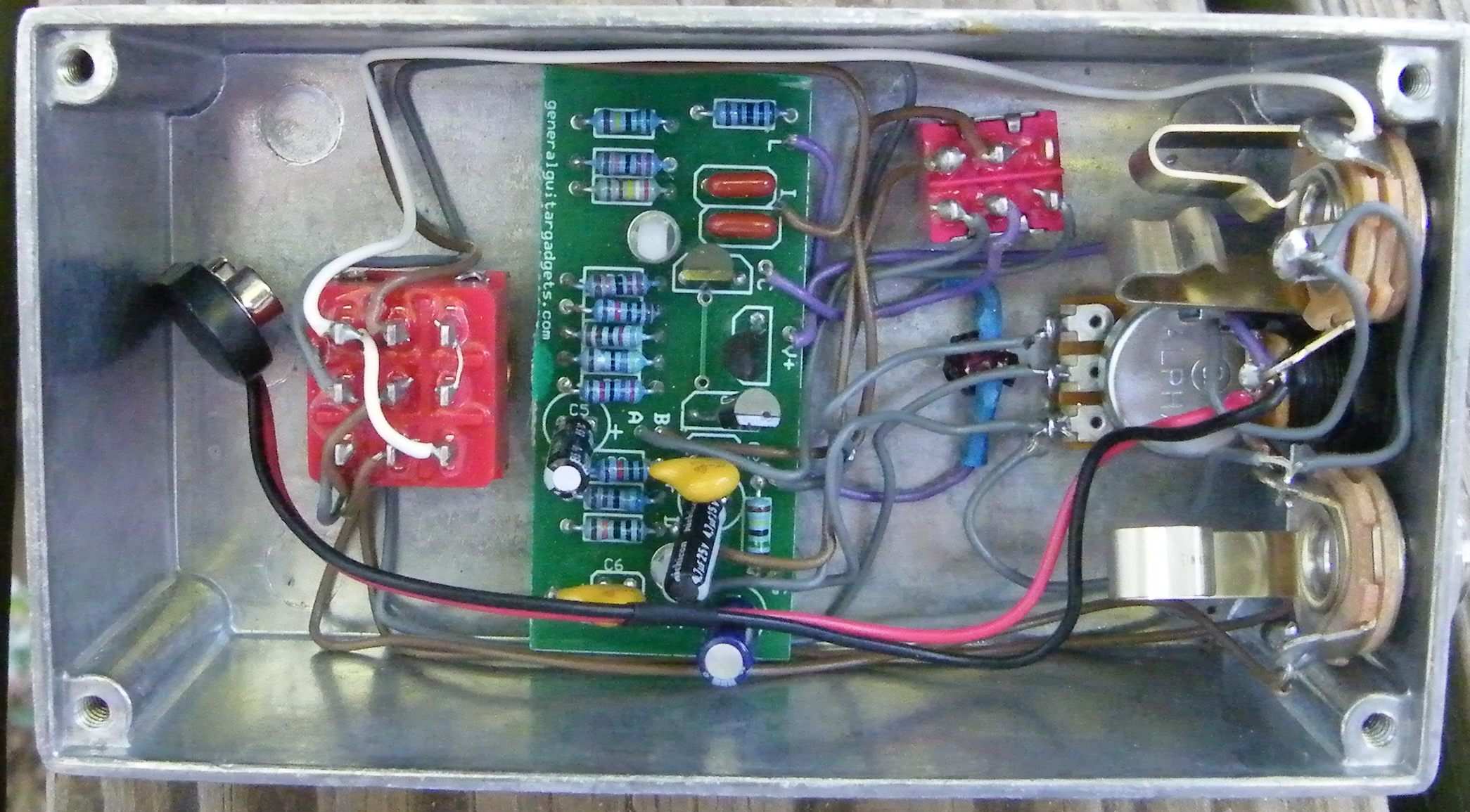
This is a very nice, clean tone booster that has a 3-way switch for 1) treble boost, 2) straight boost 3) bass boost. The original unit plugged right into a guitar jack, this is a stompbox version with true-bypass and also has a volume control which the original did not have. We prefer a linear taper 100k pot for the volume, but a log taper can be used with good results and other values should also work fine. Building the kit is very straight forward. Follow the General Instructions. The toggle switch is a standard DPDT on-off-on switch. On the following page is an inside view of the unit we built to give you a real view of our construction.
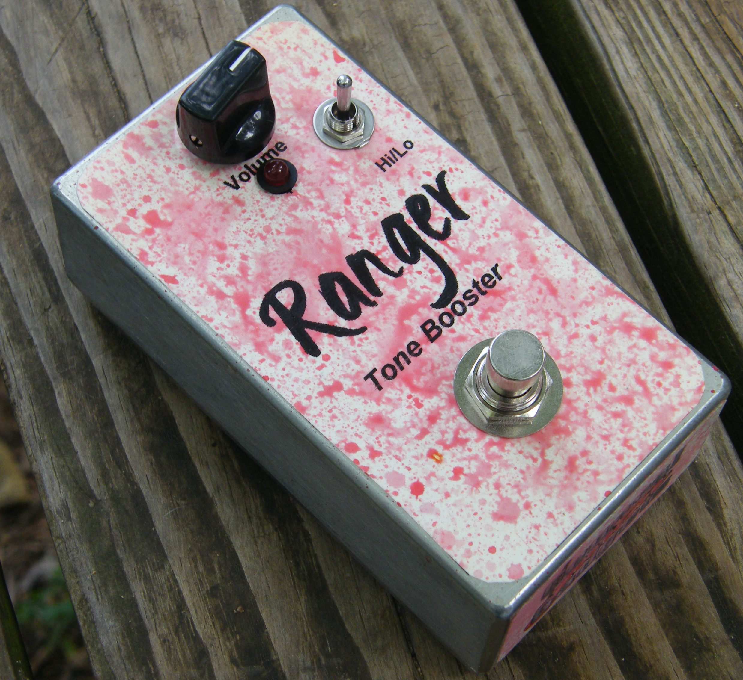
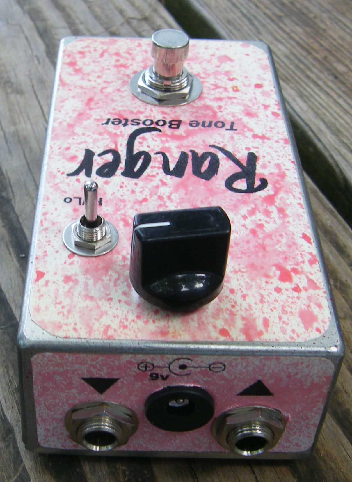
Trademarks belong to their owners, not General Guitar Gadgets
Here is a chart of voltages taken at the IC pins. Use these voltages as a guideline. You may not get the exact readings listed, but should be somewhere in the area.
Component
Location
9 volt power supply Q1
Q2
Q3
Voltage
9.7v
Emitter
4.3v
Base
4.8v
Collector
9.1v
Emitter
4.3v
Base
4.8v
Collector
9.7v
Emitter
9.7v
Base
9.1v
Collector
4.8
More about this project
Notes, sounds and related links

Ready to build? We have the kit.
Would you like a Ready to Solder Circuit Board for this project? Note: If you buy the kit, the Ready-to-Solder Printed Circuit Board (RTS PCB) is included in the kit. You do not need to purchase this Ready to Solder Circuit Printed Board if you buy the kit.