
Project · Amps
LM384 Practice Amp
This is an easy-to-build 5-watt Practice Amp, based on the 16 pin LM384 IC. You supply the speaker (almost any speaker will do). The amp is the same power amp as one of the small Marshall™ practice amp power amp stages. This project can be used as a modular building block to a full featured practice amp,or is great by itself with any stompbox between the guitar and amp (can sound dull with passive guitar pickups straight into it).
Project files
Everything you need to build it
Schematic
Schematic
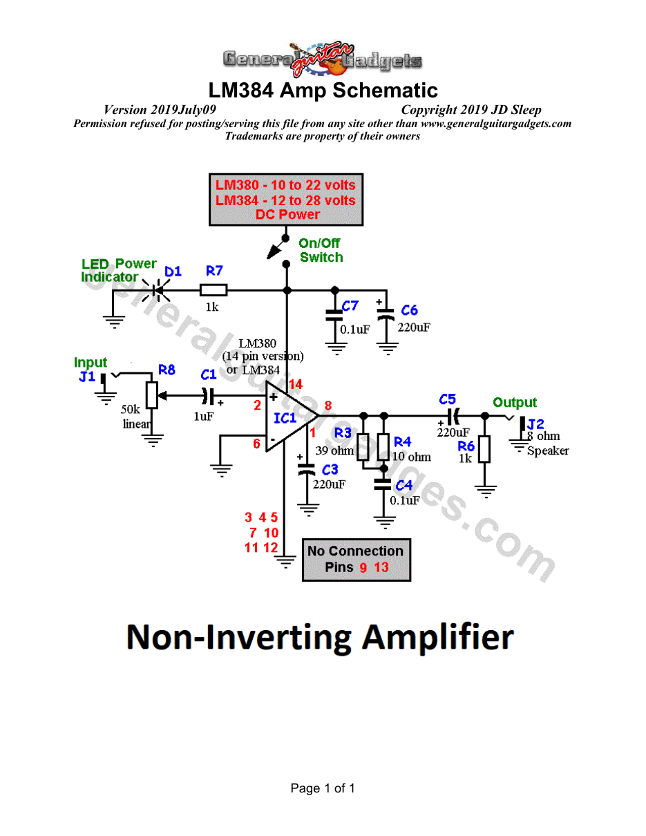
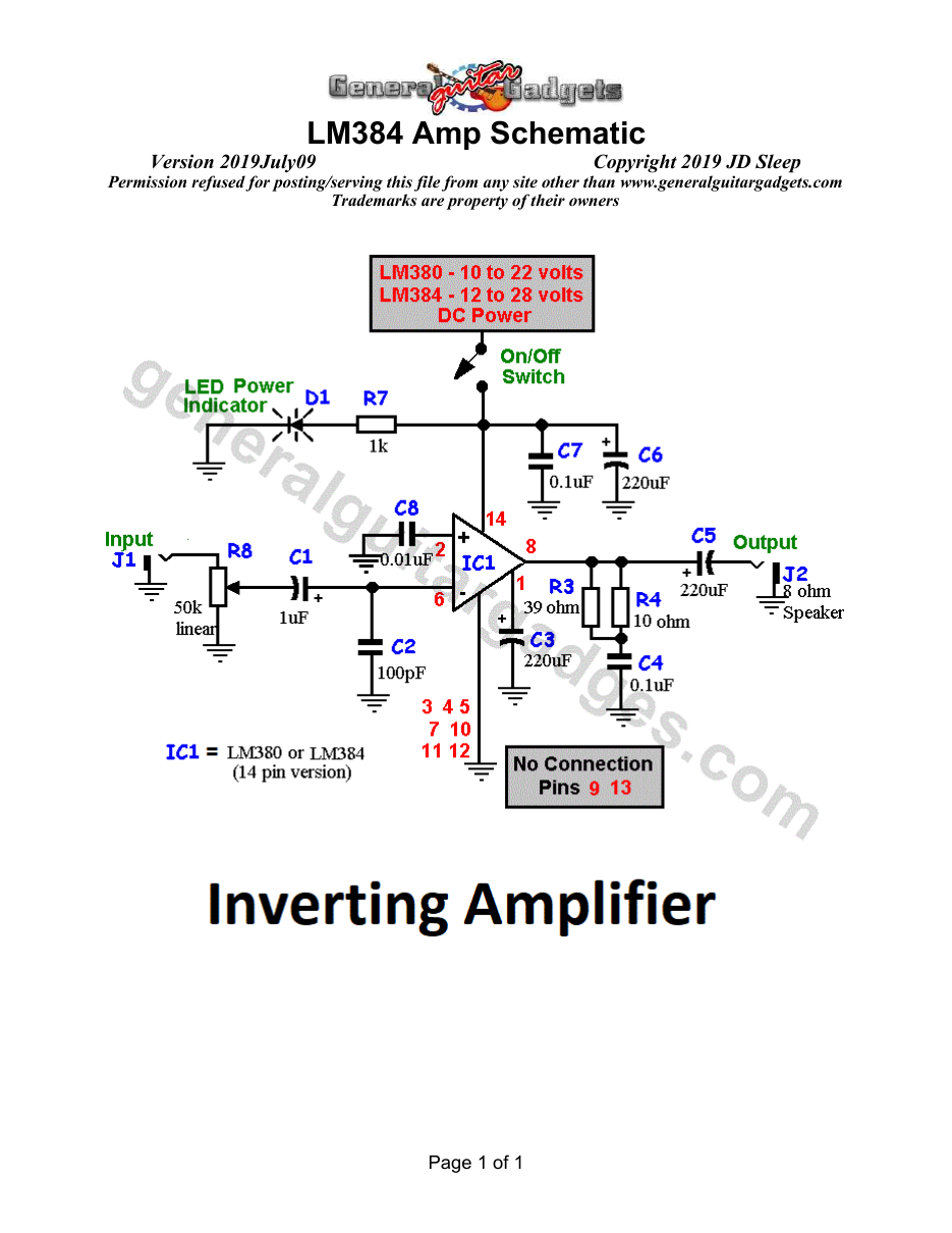
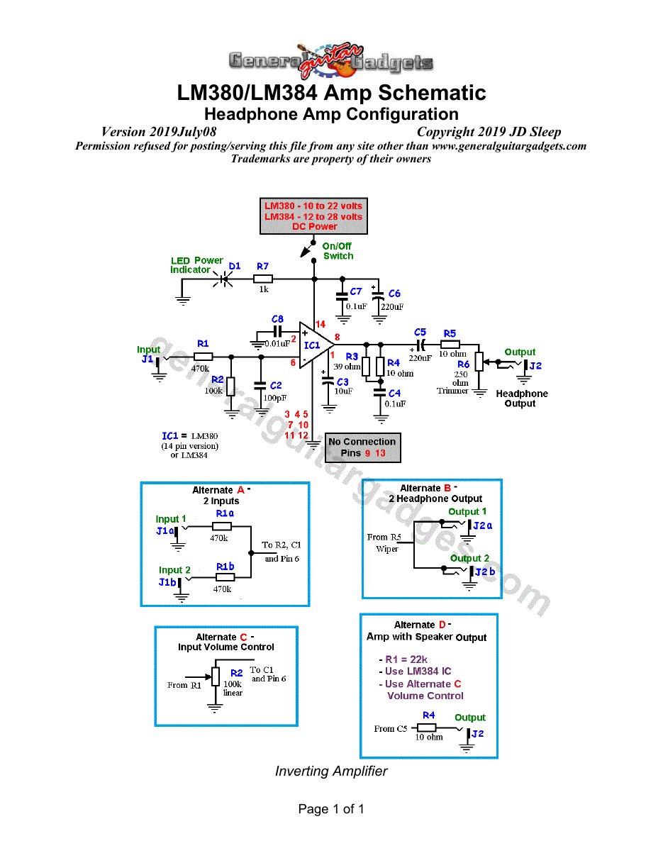
Parts layout
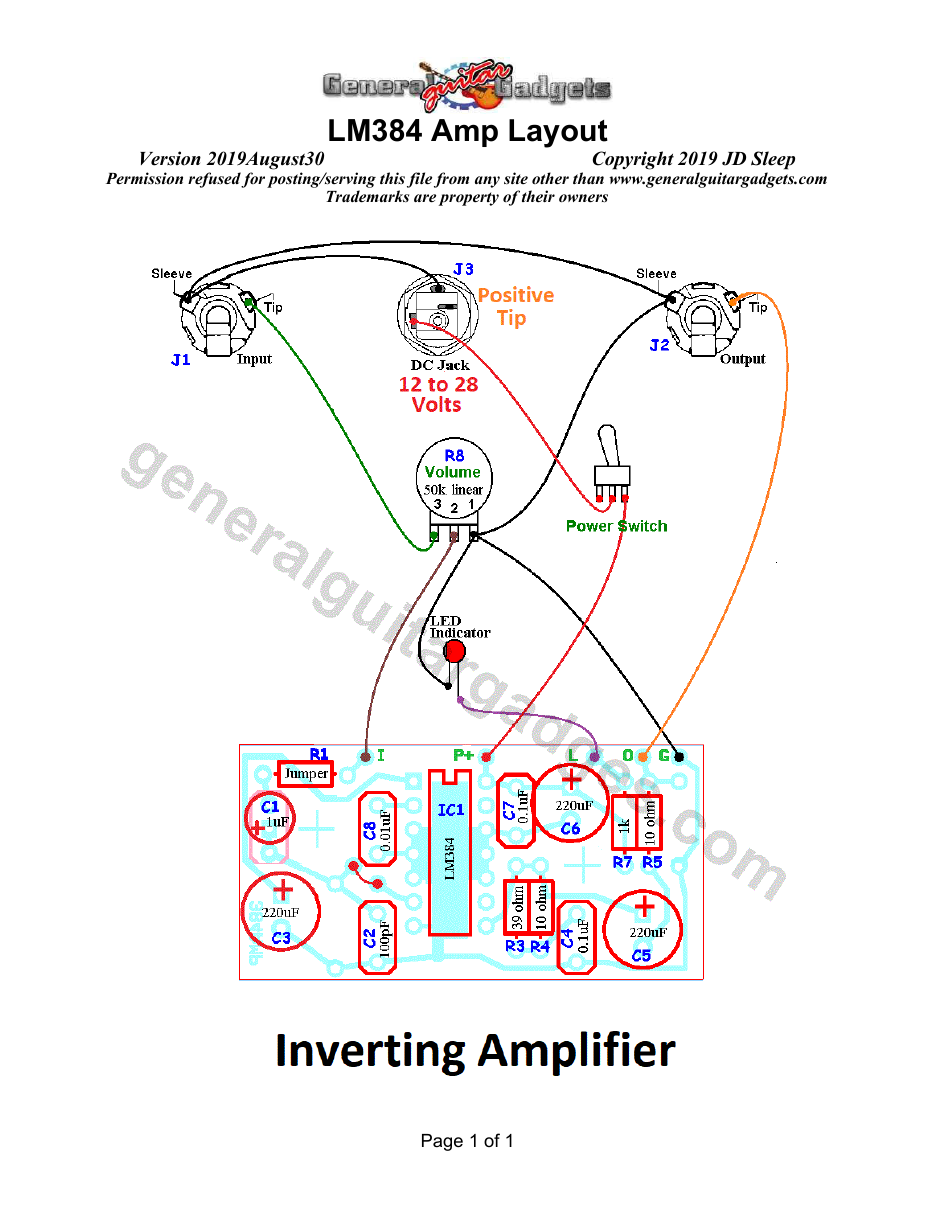
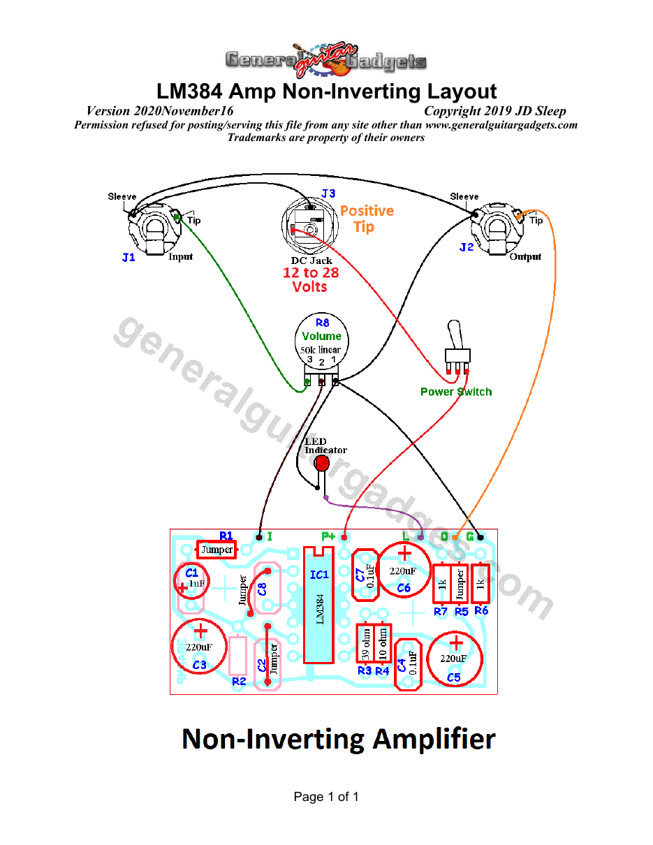
Parts Layout / Wiring Diagram
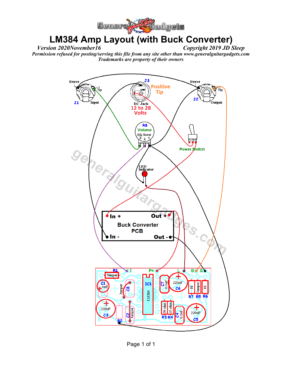
What you will need
Bill of Materials
Version 2019July21 · Copyright 2019 JD Sleep · Permission refused for posting/serving this file from any site other than www.generalguitargadgets.com · Trademarks are property of their owners
Resistors
| Resistor ID | Value | 3-band Marking | 4-band Marking |
|---|---|---|---|
| R1 | Jumper | black | black |
| R2 | None | ||
| R3 (8 ohm) | 39 ohm | orange-white-gold-gold | orange-white-black-gold |
| R4 (8 ohm) | 10 ohm | brown-black-black | brown-black-black-gold |
| R3 (4 ohm) | 30 ohm | orange-black-gold-gold | orange-black-black-gold |
| R4 (4 ohm) | 4.75 ohm | yellow-violet-gold-gold | yellow-violet-silver-brown |
| R3 (16 ohm) | 82 ohm | gray-red-gold-gold | gray-red-black-gold-brown |
| R4 (16 ohm) | 20 ohm | red-black-gold-gold | red-black-black-gold-brown |
| R5 | Jumper | black | black |
| R6 | 1k | brown-black-red | brown-black-black-brown |
| R7 | 1k | brown-black-red | brown-black-black-brown |
| R8 Volume Control Potentiometer | 50k Linear |
Capacitors
| Capacitor ID | Value | Type | Possible Marking |
|---|---|---|---|
| C1 | 1µF | Aluminum Electrolytic, or Tantalum | 1µF |
| C2 | Jumper | black | black |
| C3 | 220µF | Aluminum Electrolytic, or Tantalum | 220µF |
| C4 | 0.1µF | Film | 104 |
| C5 | 220µF | Aluminum Electrolytic, or Tantalum | 220µF |
| C6 | 220µF | Aluminum Electrolytic, or Tantalum | 220µF |
| C7 | 0.1µF | Film | 104 |
| C8 | Jumper |
Other
| Part ID | Part Name |
|---|---|
| IC1 | LM384 (14 pin) |
| IC Socket | 14pin DIP |
| D1 | LED (status indicator) (with mounting clip) |
| J1 (Guitar Input) | Mono quarter-inch jack |
| J2 (Speaker Ouptut | Mono quarter-inch jack |
| J3 | DC Jack |
| Power Supply | 12 to 28 volts DC At least 500mA Printed Circuit Board, 24 gauge stranded wire, Enclosure, Knob |
How to build it
Instructions
Version 2019July21 · Copyright 2019 JD Sleep · Permission refused for posting/serving this file from any site other than www.generalguitargadgets.com · Trademarks are property of their owners
This is the instructions and notes for the LM384 14 pin IC Amplifier (5 watt audio power amplifier). This amplifier is also completely compatible with the LM380 14 pin IC 2.5 watt audio power amplifier), just be cautious about the power supply differences if you use the LM380 IC.
Kit Instructions
If you bought the Kit for this project it is supplied with the parts for the noninverting practice amplifier. The kit does not include a speaker cabinet or speaker connection cable. So you can use your own cabinet and parts are supplied in the kit to built it for 4 ohm, 8 ohm or 16 ohm speaker connection. It is a good idea to read the General Notes below even if you are building from the kit, but the kit is simple and easy to build if you just follow the schematic and a few simple instructions. The kit includes a positive-tip 24 Volt 0.64 Amp 15.1 Watt DC Power wall adapter for powering the amp. This makes it extremely easy to build the kit and the amp can be housed in a small enclosure. We have marked the plug on the power supply in red since it is different polarity and voltage that other power supplies you may have for guitar effects. Please use caution with this power supply
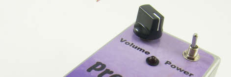



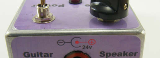
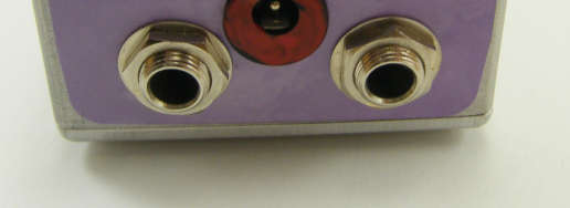
and think carefully when you have it on hand so that you don’t cause damage to any guitar effects by accidentally plugging it into a guitar effect. The Zobel Network consisting of R3, R4 and c4 can be altered according to what your speaker impedance is. Here is a table of resistor values depending on your speaker impedance: Speaker Impedance R3 R4 4 ohm
30 ohm
4.75 ohm
8 ohm
39 ohm
10 ohm
16 ohm
82 ohm
20 ohm
Build the PCB and wiring according to the Wiring Diagram/parts layout. Below is a photo for reference.



- PCB Instructions and General Notes about the Amplifier
- We have posted Non-inverting and inverting examples along with various options and
- suggestions to make it a headphone amp as well. The headphone amp is the Craig
- Anderton Headphone Amp from his Electronic Projects For Musicians (EPFM) book
- (Project 4) and the inverting amp is a simplified version of the power amp section of
- some small Marshall™-brand small practice amps. This amplifier can be used for
- headphone (as in the Anderton book) or for speaker output.
- These little low-watt amps are surprisingly good sounding amps, especially
- considering the low part count of the circuits. With the LM384 into a 10 inch (or 12
- inch) 8 ohm speaker you will get a good volume and overall great sound for a
- practice amp, much better than the LM386 practice amps such as the “Smokey”, etc.
- No preamp is needed, but there is some fidelity loss due to the high impedance guitar
- pickup going straight into the low impedance input of the power amp. an EQ pedal or
- most any guitar pedal (or buffer pedal) between the guitar and amp is all you need,
- but you can use a more traditional preamp.
- Here are some notes about the schematics:
The LM380 and the LM384 IC are pin compatible, so you can build the amp to accommodate either of these ICs with no modifications. As of the “Version Date” of this document both of these ICs are still available from Texas Instruments and are not obsolete. On the Headphone amp, R1 and R2 provide attenuation on the input. If you are always playing with a distortion pedal into the amp, the amp distortion may not be a problem for you and you can leave them off for a higher volume amp output. You can tweak the values of these resistors to suit your needs. The higher the resistance of R1 and R2, the lower the overall volume of the amp. We found R1 at 470k to be good for a headphone amp. The power voltage requirements are shown on the schematics. Both ICs will run with power voltage in the range of voltages shown on the schematics. Both ICs have a peak current listed at 1.3 amps on the datasheets, We measured the current on our LM384 amp with buffered guitar input peaking out at around 160mA (with 24v power supply). You should use a power supply with a voltage and current rating as specified in the datasheet. If you are going to build an amp with a transformer and regulator inside the enclosure
with the amp, a transformer current rating of 1 amp rating or higher might be appropriate. With a power supply of sufficient current output you won’t need to be concerned about insufficient current corrupting the sound quality of the amp. If the amp output is to a speaker, the speaker can be impedance value you want. R3 (and R4 in parallel if needed) and C4 form a Zobel network. R3 (with R4) should equal the approximate impedance (4 ohm, 8 ohm, 16 ohm, etc) of the speaker your will be using. We chose an 8 ohm speaker so the values are as close to 8 ohm as we can get. You can use an online “parallel resistor calculator” to find the resistor values you need, since they don’t make 4, 8 or 16 ohm resistors, you can combine values to get close to the desired impedance match. The current limiting resistor (CLR) for the LED (R4 in the schematics) is 1k value, but it can be any value from 470 ohm up to 10k or more depending on what LED you are using and how bright you want it and how much current you want to the LED to consume. The higher the CLR value the dimmer the LED will be and the less current will be used by the LED. Of course it can be built without the LED and CLR, just leave them out. These ICs may need a heat sink. The ICs have internal thermal shutdown circuits to prevent them from melting down, but you won’t want them going into thermal-shutdown just when you start to groove! Heat sinks are available for 14 pin DIP ICs, but we didn’t have any problems with over heating even in high ambient temperatures (90 degree F in the test environment). You can put volume control on the front of the circuit or at the end, or both if you want. You could use trim pots or panel mount pots in either positions as suits your needs best. The Anderton schematic has two inputs and two outputs (for headphones). If you want two outputs, just put the outputs in series. For two inputs, put them in series after the 470k, so you would need another 470k resistor if you are going to use 2 inputs.
More about this project
Notes, sounds and related links
These are the LM384 5-watt Practice Amp, Inverting amps including headphone amp. In case for some reason you would like to build it "inverting". Also a simple non0inverting layout diagram is included below.


Ready to build? We have the kit.
Buy a LM384 Practice Amp Complete Kit. Includes all the parts and materials you need to build one, all for about the price you would pay for a PCB and parts.
Would you like a Ready to Solder Circuit Board for this project?