
Project · Tremolo
Craig Anderton's Tremolo Project
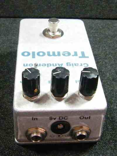
This is a very nice Tremolo. Check out the sound demo below. It has a switch for triangle or square wave and the optical circuit is clear and quiet.
Project files
Everything you need to build it
Anderton Tremolo Ready-For-Transfer Printed Circuit Board Layout
Schematic
Schematic
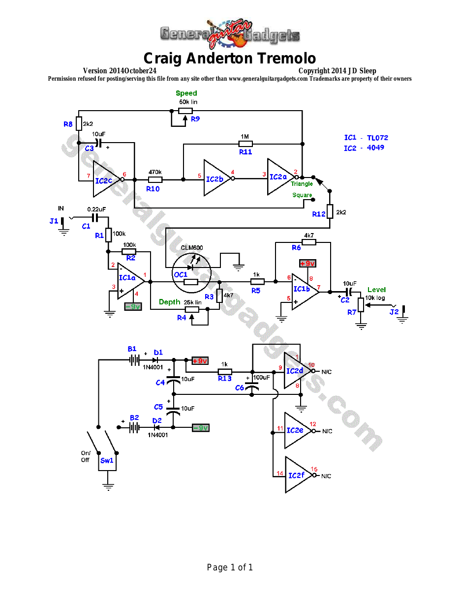
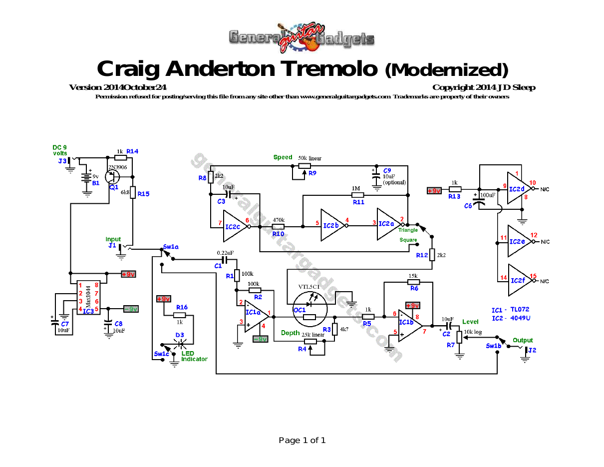
Parts layout
Parts Layout / Wiring Diagram
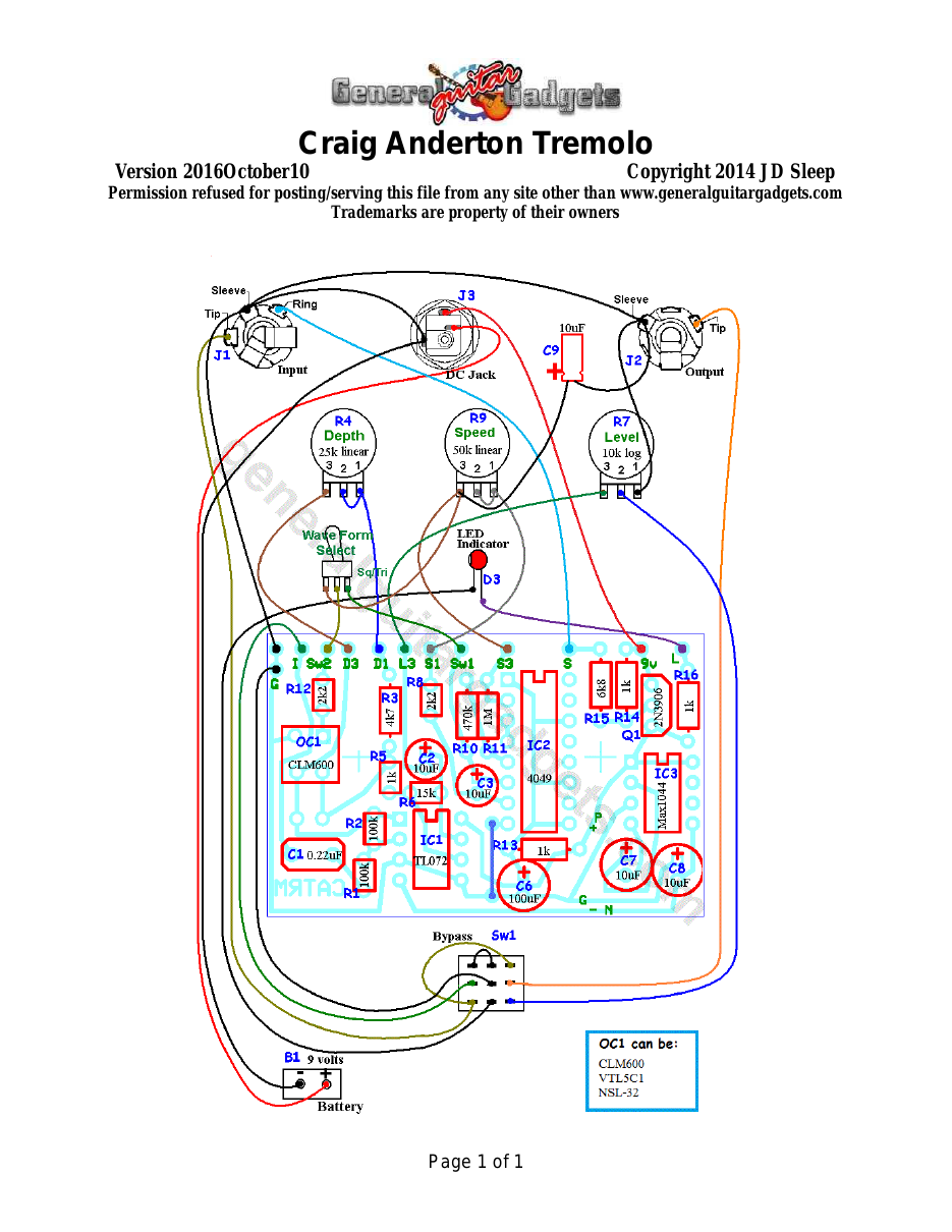
What you will need
Bill of Materials
Version 2015July20 · Copyright 2014 JD Sleep · Permission refused for posting/serving this file from any site other than www.generalguitargadgets.com · Trademarks are property of their owners
Resistors
| Resistor ID | Value | 3-band Marking | 4-band Marking |
|---|---|---|---|
| R1 | 100k | brown-black-yellow | brown-black-black-orange |
| R2 | 100k | brown-black-yellow | brown-black-black-orange |
| R3 | 4k7 (4.7k) | yellow-violet-red | yellow-violet-black-brown |
| R4 (Depth Control) | 25k Linear Potentiometer | ||
| R5 | 1k | brown-black-red | brown-black-black-brown |
| R6 | 15k | brown-green-orange | brown-green-black-red |
| R7 (Level Control) | 10k Log Potentiometer | ||
| R8 | 2k2 (2.2k) | red-red-red | red-red-black-brown |
| R9 | 50k Linear Potentiometer | ||
| R10 | 470k | yellow-violet-yellow | yellow-violet-black-orange |
| R11 | 1M | brown-black-green | brown-black-black-yellow |
| R12 | 2k2 (2.2k) | red-red-red | red-red-black-brown |
| R13 | 1k | brown-black-red | brown-black-black-brown |
| R14 | 1k | brown-black-red | brown-black-black-brown |
| R15 | 6k8 (6.8k) | blue-gray-red | blue-gray-black-brown |
| R16 | 1k | brown-black-red | brown-black-black-brown |
Capacitors
| Capacitor ID | Value | Type | Possible Marking |
|---|---|---|---|
| C1 | 0.22µF | Film | 224 |
| C2 | 10µF | Tantalum or Aluminum Electrolytic | 10µF |
| C3 | 10µF | Tantalum or Aluminum Electrolytic | 10µF |
| C4 | None | ||
| C5 | None | ||
| C6 | 100µF | Aluminum Electrolytic | 100µF |
| C7 | 10µF | Tantalum or Aluminum Electrolytic | 10µF |
| C8 | 10µF | Tantalum or Aluminum Electrolytic | 10µF |
| C9 (optional) | 10µF | Tantalum or Aluminum Electrolytic | 10µF |
Potentiometers
| Part ID | Value | Type |
|---|---|---|
| R7 - Depth | 25k | Linear Taper Potentiometer |
| R7 - Level | 10k | Log (Audio) Taper Potentiometer |
| R9 - Speed | 50k | Linear Taper Potentiometer |
Other
| Part ID | Part Name |
|---|---|
| Q1 | 2N3906 |
| IC1 | TL072 Opamp |
| IC2 | 4049U |
| IC3 | MAX1044 Charge Pump |
| OC1 | CLM600, VTL5C1 or DIY LED/LDR unit |
| D3 | Status Indicator LED and holder |
| J1 | Stereo quarter-inch jack |
| J2 | Mono quarter-inch jack |
| J3 | DC Jack |
| B1 | 9 volt battery (not included in the Kit) |
| Sw1 | Heavy Duty 3PDT Foot Switch |
| Sw2 | SPDT Toggle Switch 9v battery snap, Printed Circuit Board, 24 gauge stranded wire, Enclosure, Knobs |
How to build it
Instructions
Version 2015July21 · Copyright 2014 JD Sleep · Permission refused for posting/serving this file from any site other than www.generalguitargadgets.com · Trademarks are property of their owners
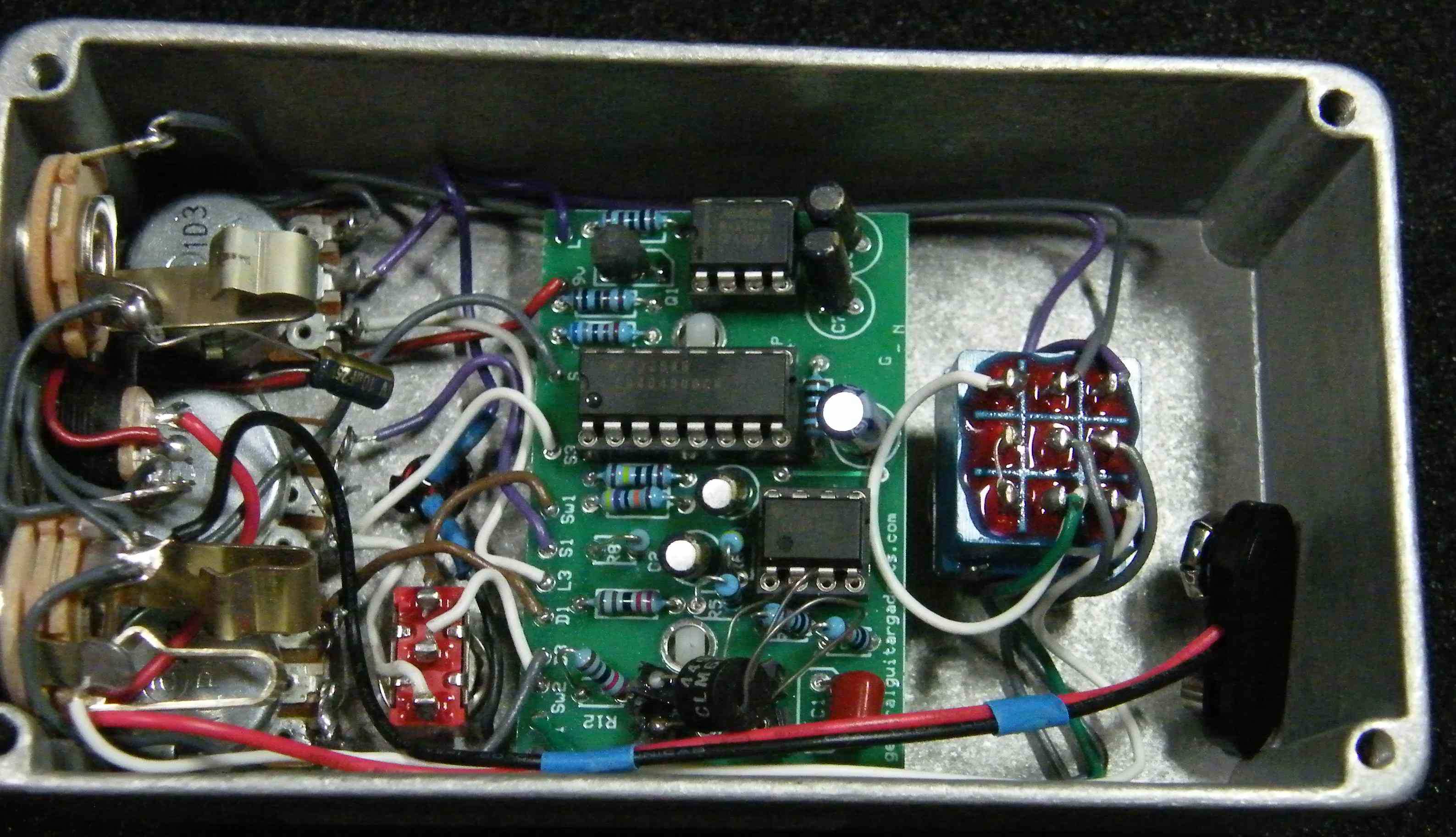
This is a great sounding, yet simple to build tremolo. It is a versatile tremolo with triangle or square wave tremolo sounds and it has a level control. It has some really cool sounds and is a very clear solid tremolo sound, as you can hear in the audio demo on the project page. Use the project documents provided, starting with the General Build Instructions. The PCB includes a charge pump IC so that you can get bipolar power supply for the circuit from a singe 9v battery or 9v DC power supply. The tremolo is produced by a fluctuating LED/LDR unit. The original specification was for a CLM600. These have been obsolete for sometime, but can still be purchased from some sources. We found that a VTL5C1 works just as well as a CLM600 and are a bit easier to find. Another possibility is to construct a DIY optical unit using a bright LED and a LDR unit put together inside shrink tube or other DIY construction as you see fit. There was clock noise (audible ticking sound) in the output signal of the unit we built. This can be eliminated by solder tacking a 10uf capacitor between lug 3 of the “Speed” control and any nearby ground point. If you look at the photo below you can see a 10uF cap soldered between the Speed control and the ground lug on the output jack. We thought the volume level was a bit low, so we replaced R6 value of 4k7 with a 15k resistor and that brings the volume level up to a better level to work with.
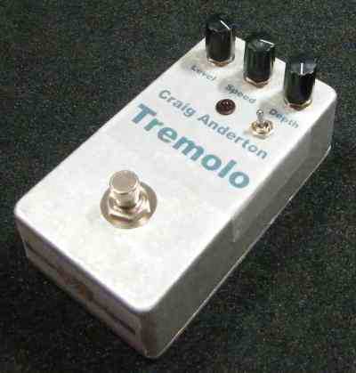
Here's an inside view of the unit we built to give you some general ideas if needed.
Here is a chart of voltages taken at the IC pins. Use these voltages as a guideline. You may not get the exact readings listed, but they should be somewhere near these values.
Component
Location
9 volt power supply IC1
IC2
Voltage
9.4v
Pin 1
0.01v
Pin 2
0.01v
Pin 3
0v
Pin 4
-9.1v
Pin 5
0v
Pin 6
0v
Pin 7
0v
Pin 8
9.3v
Pin 1
5.5v
Pin 2
Varies with Speed control
Pin 3
Varies with Speed control
Pin 4
Varies with Speed control
Pin 5
Varies with Speed control
Pin 6
Varies with Speed control
Pin 7
2.6v
Pin 8
0v
Pin 9
5.5v
Pin 10
0v
Pin 11
5.5v
Pin 12
0v
Pin 13
0v
Pin 14
5.5v
IC3
Pin 15
0v
Pin 16
0v
Pin 1
9.3v
Pin 2
4.6v
Pin 3
0v
Pin 4
-4.6v
Pin 5
-9.1v
Pin 6
4.7v
Pin 7
7.0v
Pin 8
9.3v
More about this project
Notes, sounds and related links
Craig Anderton Tremolo Sound Demo