
Project · Reverb
Digital Reverb
This is a great sounding digital reverb project. Based on the Belton BTDR-2 or BTDR-3 Digital Reverb Brick.
The story
About the circuit
For most of the DIY era, reverb meant a spring tank and a lot of enclosure. That changed when Belton (the Accutronics spring-reverb company) released the BTDR "Digital Reverb Brick," a small sealed module built around three cascaded delay chips that produces a convincing spring-style reverb with no tank, no high voltage and no noise problems. It needs a handful of parts around it to become a pedal: a buffer, a mix control, and a power supply. Almost every DIY and boutique digital reverb pedal of the 2010s is built on one.
This project at GGG
The D-Verb is our pedal built around the Belton brick (BTDR-2 or BTDR-3), with the input and output buffering and the mix control laid out on one board so the module just plugs in. It is the one reverb we sell as a complete kit, and it is a good first "non-dirt" pedal: the build is simple, the result sounds like a studio spring unit, and it fits a normal pedalboard. The schematic and layout are below.
Project files
Everything you need to build it
D-VERB Ready-For-Transfer Printed Circuit Board Layout - For use only if you are a complete DIY person who wants to etch and drill your own PCB. Otherwise, we recommend you ignore this PCB mask and buy the Ready-to-Solder Printed Circuit Board or Complete Kit.
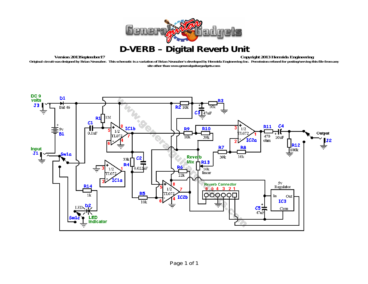
Parts layout
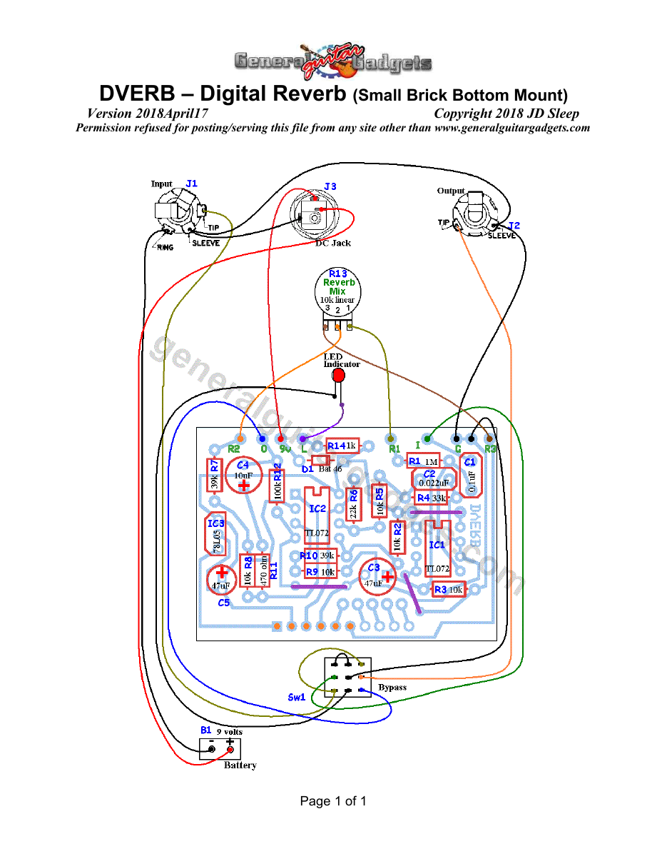
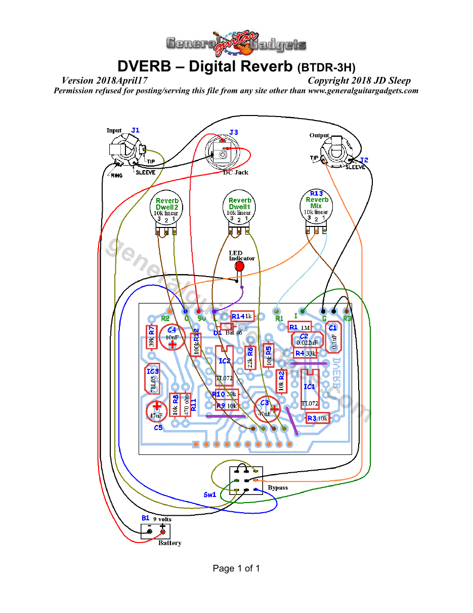
Parts Layout / Wiring Diagram
What you will need
Bill of Materials
Version 2013September28 · Copyright 2013 JD Sleep · Permission refused for posting/serving this file from any site other than www.generalguitargadgets.com · Trademarks are property of their owners
Resistors
| Resistor ID | Value | 3-band Marking | 4-band Marking |
|---|---|---|---|
| R1 | 1M | brown-black-green | brown-black-black-yellow |
| R2 | 10k | brown-black-orange | brown-black-black-red |
| R3 | 10k | brown-black-orange | brown-black-black-red |
| R4 | 33k | orange-orange-orange | orange-orange-black-red |
| R5 | 10k | brown-black-orange | brown-black-black-red |
| R6 | 22k | red-red-orange | red-red-black-red |
| R7 | 39k | orange-white-orange | orange-white-black-red |
| R8 | 10k | brown-black-orange | brown-black-black-red |
| R9 | 10k | brown-black-orange | brown-black-black-red |
| R10 | 39k | orange-white-orange | orange-white-black-red |
| R11 | 470 ohm | yellow-violet-brown | yellow-violet-black-black |
| R12 | 100k | brown-black-yellow | brown-black-black-orange |
| R13 (potentiometer) | 10k Linear | ||
| R14 | 1k | brown-black-red | brown-black-black-brown |
Potentiometers
| Part ID | Value | Type |
|---|---|---|
| R13 – Reverb Mix Control | 10k | Linear Taper |
Capacitors
| Capacitor ID | Value | Type | Possible Marking |
|---|---|---|---|
| C1 | 0.1µF | Film or ceramic | 104 |
| C2 | 0.022µF | Film or ceramic | 223 |
| C3 | 47µF | Aluminum Electrolytic | 47µF |
| C4 | 10µF | Aluminum Electrolytic | 10µF |
| C5 | 47µF | Aluminum Electrolytic | 47µF |
Other
| Part ID | Part Name |
|---|---|
| IC1 | TL072 |
| IC2 | TL072 |
| IC3 | 5 volt regulator TO-92 |
| D1 | BAT 46 |
| D2 | LED |
| J1 | Stereo quarter-inch jack |
| J2 | Mono quarter-inch jack |
| J3 | DC Jack |
| B1 | 9 volt battery (not included in the Kit) |
| Reverb Unit | Accutronics Digi-Log Reverb Unit Model:BTDR-2H |
| Sw1 | Heavy Duty 3PDT footswitch 9v battery snap, Printed Circuit Board, 24 gauge stranded wire, Enclosure, knob |
How to build it
Instructions
Copyright 2013, 2018JD Sleep · Permission refused for posting/serving this file from any site other than www.generalguitargadgets.com · Trademarks are property of their owners
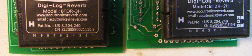
This is the D-VERB (Digital Reverb) kit. It is an excellent sounding reverb pedal, simple to build and compact for the pedal board. The source of the reverb sound is a digital reverb module made called Digi-LogTM Reverb by Accutronics. As of December 2017 The PCB accommodates the BTDR-2 or the BTDR-3 model of the module. Throughout this document we will refer to these modules as the “brick”. If you are building with the BTDR-2 brick with 6 pins, don’t freak out about the 4 empty pin holes for the brick on the PCB, it will work as expected. 1. Install the resistors on the PCB as shown in the parts layout diagram. 2. Install the capacitors, the 7805 and the TL072 ICs. We recommend IC sockets. 3. Solder the off-board wires to the PCB 4. Solder the reverb brick to the PCB, positioning the PCB on the bottom of the PCB. Pin 1 of the brick is in the square hole. The brick is directly below the PCB. Double check the orientation of the brick before you start. It can be confusing since you are soldering it to the bottom of the PCB. Remember, the BTDR-2 will only occupy only the first 6 holes, the BTDR-3 brick will fill all the holes.
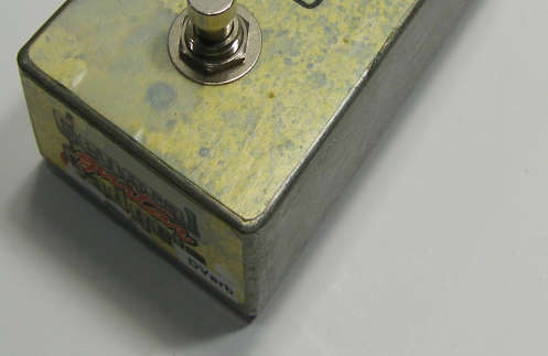
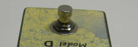
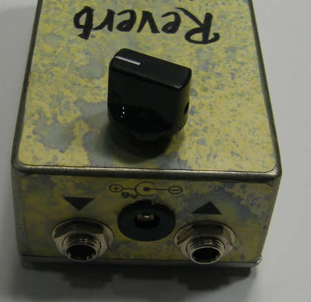
5. Solder wiring to the LED short lead to the foot switch. 6. Use double sided foam tape to attach the top of the brick to the top inside of the enclosure. 7. Wire the PCB wires to the pot, DC jack, ground and foot switch. 8. Wire the in/out jacks to ground and to the foot switch. 9. Solder in the battery snap.
Here are some observations we made and opinions we formed when building with both of the brick types: Both the BTDR-2 and the BTDR-3 were designed for mono or stereo outputs. It is our opinion (and a declaration to the designers of the bricks): unless you have stereo inputs, with the stereo sound passing through the effect intact, the “stereo output option has a very limited application in today’s world of stereo guitar effects. We don’t have diagrams to accommodate stereo outputs, but it is a fairly simple matter to add the additional output for stereo if you are so inclined. It has been suggested by someone on a forum that when building a mono output effect, you will get deeper reverb sound if you connect both “stereo” “Reverb” controls (pins 5 and 6 are what we call “Reverb Mix” or “Depth”) to the potentiometer control. Our testing has found this to be untrue on the BTDR-2 and BTDR-3 bricks with our PCB. Our schematic and layouts only have this control from one pin (pin 6). The sound is the same whether you use Depth control from pin 5 or pin 6. It is the same depth using just one of the pins or using both pins 5 and 6 together out to the same pot or pins 5 and 6 out to separate depth pots. It just doesn’t give you any better or deeper sound trying to use both output in mono. There are, most likely, useful possibilities for the second output, with some ingenuity and added circuitry, it may prove useful. But those options are beyond the scope of this project. With the BTDR-3, both “Dwell” controls (or “Depth” as it is labeled on the data sheet) must be engaged (wired to potentiometers) whether in stereo or mono mode. If you leave one open without wiring it to a pot, the Dwell for that control is still heard, defaulting to the low setting. This is obviously another silly “feature” from the designers of the brick. The data sheet shows it wired to a dual-gang pot and so it must be (or to two separate pots). We found it to be worth while to wire the Dwell to two separate pots. You can clearly hear when one is low and one is high and it is a cool effect. They can both be set the same or nearly the same for “normal” dwell effect. You can wire them the same way as shown in our diagram onto a dual gang 10k B pot if you like. In your mind, just sort of stack the two pots into a dual-gang pot
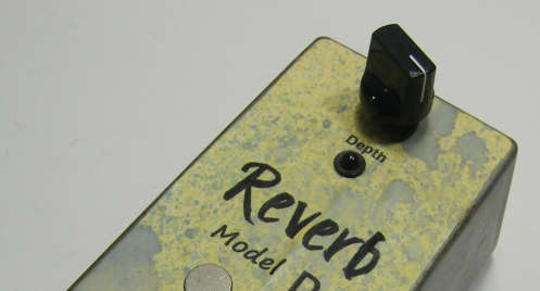
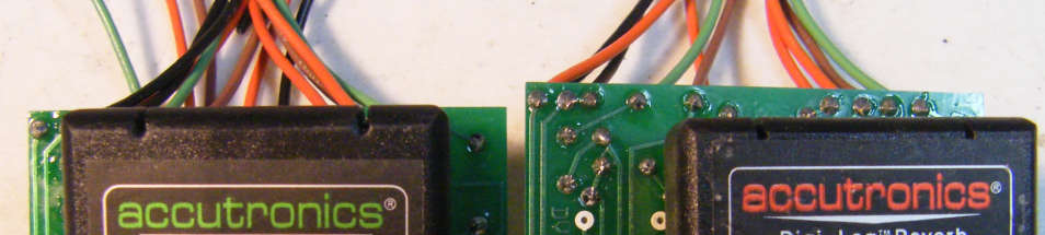
formation. Our last observation is that when the dwell control is on full using the BTDR-3, it sounds about the same as the BTDR-2 version. Our preference for this stompbox is the simple one knob version using the BTDR-2 brick. There are more variety of sounds from the BTDR-3 brick, so make your choice between a very nice simple reverb (BTDR-2) or adding the dwell (BTDR-3) if you like that particular sound. Here are some inside views of the units we built to give you a real view of the construction.






Here is a chart of voltages taken at the IC pins. This information can be used to help you find and fix problems if your DVERB doesn't work when you test it. The voltages are approximate, you may not get these exact readings, but they should be somewhere close. Also, the voltage on the surface mount regulator pin closest to the edge of the PCB should be 5v. Check that voltage so you know that the “Brick” is getting 5v power.
Component
Location
9 volt power supply IC1
IC2
Voltage
9.4v
IC Pin 1
8.2v
IC Pin 2
8.2v
IC Pin 3
0v
IC Pin 4
0v
IC Pin 5
3.9v
IC Pin 6
4.4v
IC Pin 7
8.8v
IC Pin 8
8.8v
IC Pin 1
4.4v
IC Pin 2
4.4v
IC Pin 3
4.4v
IC Pin 4
0v
IC Pin 5
4.4v
IC Pin 6
4.4v
IC Pin 7
4.4v
IC Pin 8
8.8v
More about this project
Notes, sounds and related links

Ready to build? We have the kit.
Buy a D-VERB Complete Kit. Includes all the parts and materials you need to build one, all for about the price you would pay for a PCB and parts.

Would you like a Ready to Solder Circuit Board for this project? Note: If you buy the kit, the Ready-to-Solder Printed Circuit Board (RTS PCB) is included in the kit. You do not need to purchase this Ready to Solder Circuit Printed Board if you buy the kit.