
Project · Octave
Tycho* Octave
This is the octave up sound similar to the Jimi Hendrix sound of the Purple Haze solo. This is the most intense of the Octave-Ups that we know of. We've added a PreGain control, so that it's possible to tone down the insanity and hear some nice Octave sounds. Check the Instructions file for details. Any trade marks or parts of trademarks mentioned here belong to their owners, not General Guitar Gadgets
The story
About the circuit
The octave-up fuzz on Jimi Hendrix's "Purple Haze" solo was built by Roger Mayer in 1967. In the mid-1970s the Tycobrahe Sound Company of Hermosa Beach, California produced its own take on the idea, and that pedal is the one this project replicates. The octave effect comes from a small audio transformer feeding a pair of germanium diodes, which full-wave rectify the signal: every negative swing is flipped positive, doubling the frequency and producing the ghostly upper octave. Driven hard, the same stage turns into one of the most intense fuzzes ever put in a box. Originals are rare and expensive, and the circuit's reputation for being wild is well earned.
This project at GGG
The TOCT has been here since the site's early days. The original pedal was positive ground, so one of the first things we did was convert it to negative ground (with thanks to Fuzz Central for part of that work) so it would run from a normal pedalboard supply. The next thing we learned, after building a few, was that the octave gets buried when the input is wide open, so we added a PreGain control: turn PreGain and Intensity down for the Hendrix octave, turn both up for chaos. The layout supports either a toggle or a second footswitch to select fuzz or octave. There is also a boutique variant with the first transistor installed backwards (emitter and collector swapped); it works, sounds slightly different, and the instructions explain how to try it.
Project files
Everything you need to build it
T - For use only if you are a complete DIY person who wants to etch and drill your own PCB. Otherwise, we recommend you ignore this PCB mask and buy the Ready-to-Solder Printed Circuit Board or Complete Kit.
Schematic
Schematic
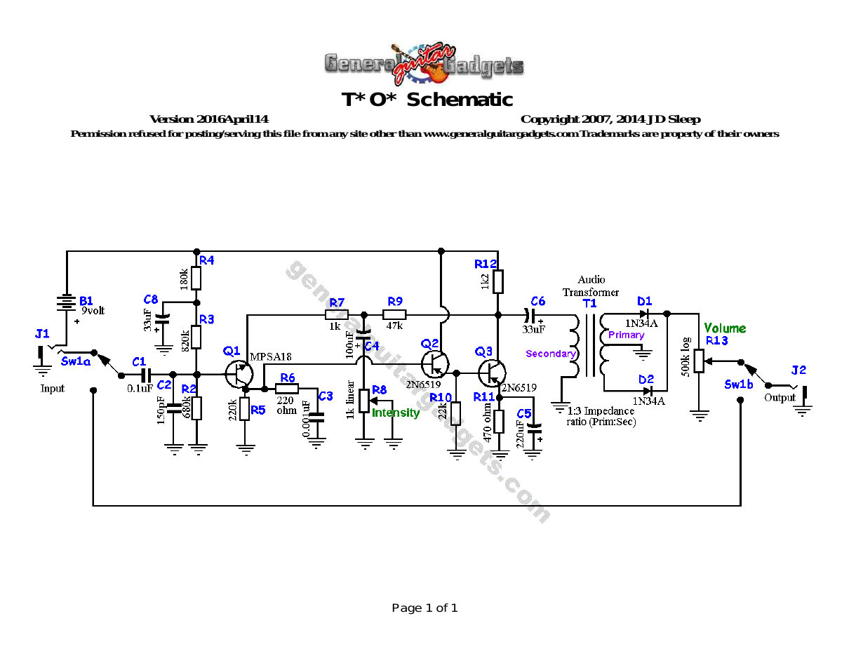
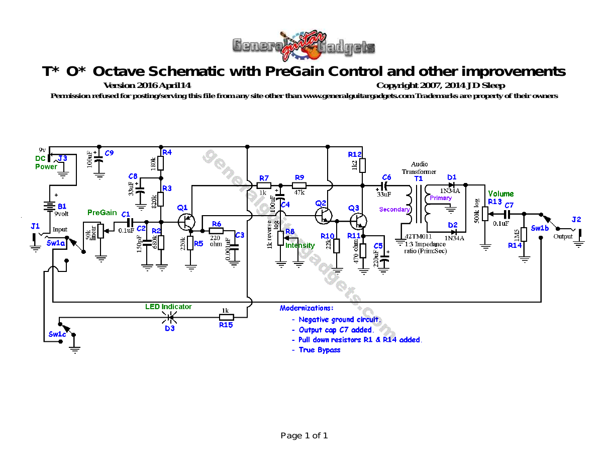
Parts layout
Parts Layout / Wiring Diagram
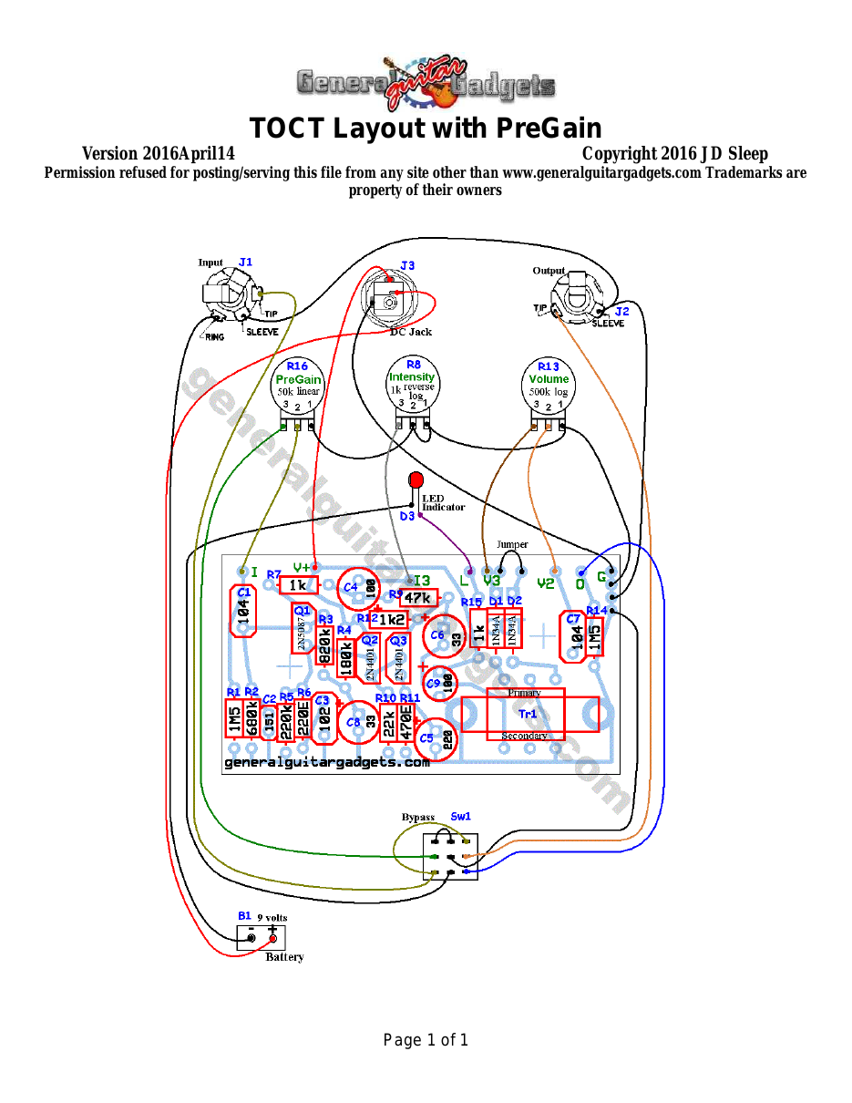
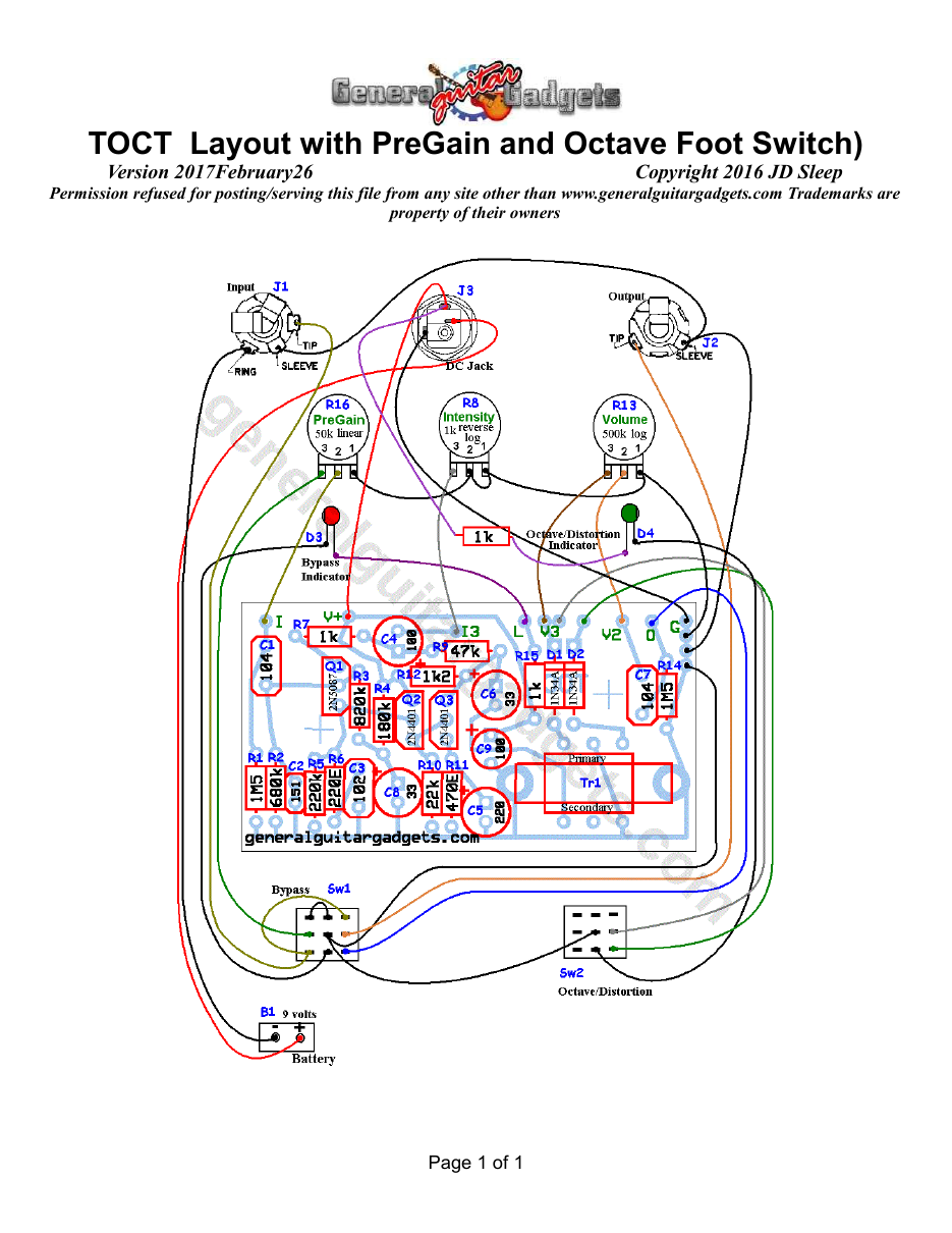
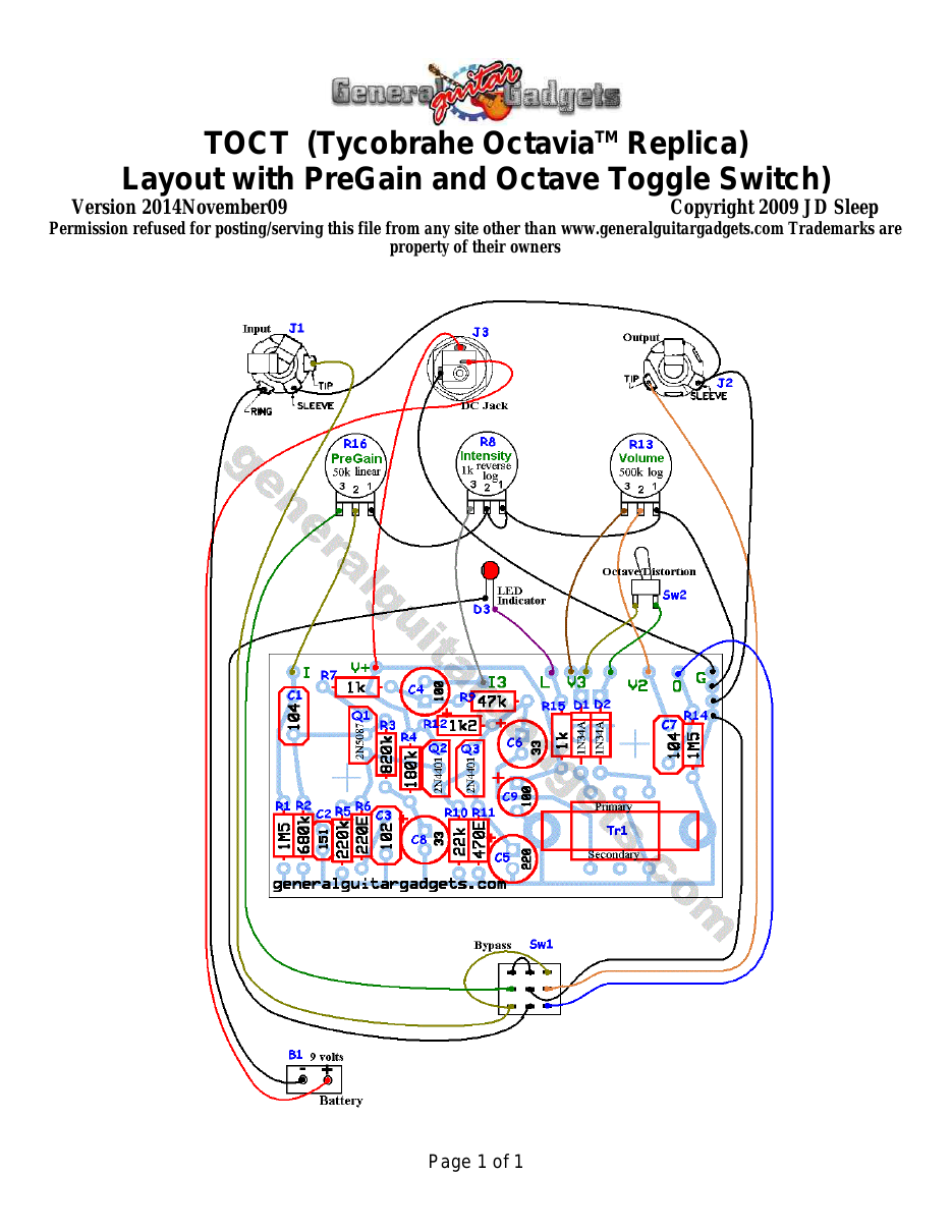
What you will need
Bill of Materials
Version 2016April14 · Copyright 2007, 2014 JD Sleep · Permission refused for posting/serving this file from any site other than www.generalguitargadgets.com · Trademarks are property of their owners
Resistors
| Resistor ID | Value | 3-band Marking | 4-band Marking |
|---|---|---|---|
| R1(Optional) | 1M5 (1.5M) | brown-green-green | brown-green-black-yellow |
| R2 | 680k | blue-gray-yellow | blue-gray-black-orange |
| R3 | 820k | gray-red-yellow | gray-red-black-orange |
| R4 | 180k | brown-gray-yellow | brown-gray-black-orange |
| R5 | 220k | red-red-yellow | red-red-black-orange |
| R6 | 220 ohm | red-red-brown | red-red-black-black |
| R7 | 1k | brown-black-red | brown-black-black-brown |
| R8 (Intensity) | 1k Reverse Log Potentiometer | ||
| R9 | 47k | yellow-violet-orange | yellow-violet-black-red |
| R10 | 22k | red-red-orange | red-red-black-red |
| R11 | 470 ohm | yellow-violet-brown | yellow-violet-black-black |
| R12 | 1k2 (1.2k) | brown-red-red | brown-red-black-brown |
| R13 (Volume) | 500k Log Potentiometer | ||
| R14 (optional) | 1M5 (1.5M) | brown-green-green | brown-green-black-yellow |
| R15 | 1k | brown-black-red | brown-black-black-brown |
| R16 (Pre-Gain) | 50k Linear Potentiometer |
Capacitors
| Capacitor ID | Value | Type | Possible Marking |
|---|---|---|---|
| C1 | 0.1µF | Film | 104 |
| C2 | 150pF | Ceramic or Film | 151 |
| C3 | 0.001µF | Film | 102 |
| C4 | 100µF | Aluminum Electrolytic | 100µF |
| C5 | 220µF | Aluminum Electrolytic | 220µF |
| C6 | 33µF | Aluminum Electrolytic | 33µF |
| C7 | 0.1µF | Film | 104 |
| C8 | 33µF | Aluminum Electrolytic | 33µF |
| C9 | 100µF | Aluminum Electrolytic | 100µF |
Potentiometers
| Part ID | Value | Type |
|---|---|---|
| R8 - Intensity Control | 1k | Reverse Log Taper |
| R13 - Volume Control | 500k | Log Taper |
| R16 - Pre-Gan Control | 50k | Linear Taper |
Other
| Part ID | Part Name |
|---|---|
| Q1 | PNP bipolar junction transistor Examples: 2N5087 or 2N3906 |
| Q2 & Q3 | NPN bipolar junction transistor Examples: 2N5088 or 2N4401 |
| D1 & D2 | 1N34A Germanium diodes |
| D3 | Bypass Status indicator LED |
| T1 | 42TM011 Audio Transformer Primary:1.5k ohm, Secondary 500 ohm or any with impedance ratio of about 3:1 |
| J1 | Stereo quarter-inch jack |
| J2 | Mono quarter-inch jack |
| J3 | DC Jack |
| B1 | 9 volt battery (not included in the Kit) |
| Sw1 | Heavy Duty 3PDT foot switch |
9v battery snap, Printed Circuit Board, 24 gauge stranded wire, Enclosure, Knobs
How to build it
Instructions
Tycho* Octave Instructions
Version 2016April14 · Copyright 2014 JD Sleep · Permission refused for posting/serving this file from any site other than www.generalguitargadgets.com · Trademarks are property of their owners
This is a replica of the octave stompbox we cannot mention by name referred to as TOCT in these documents. This Octave/Fuzz is extreme by most standards. Thanks to Fuzz Central for some of the information to make this a Negative-Ground circuit. The transistor selection can make some difference in the sound, but it is not critically important to getting a good sound. We have added a PreGain feature on this project since we noticed that the Octave sound is hard to achieve without tuning down the input some. For full out insanity, leave the PreGain and Intensity controls on full. Turn down both PreGain and Intensity to get good Hendrix type Octave sounds. There is an option for a toggle switch to select between Fuzz and Octave, but we built this one without since we wanted a straight up Octave box. With Intensity and PreGain on full, the Octave is somewhat "lost in the storm", with sounds of very, very intense fuzz. You should be able to get lots of controlled feedback and swells on most amps even at moderate and low volume levels. Positioning of Q1. There is a boutique version of this circuit that has the Q1 transistor reversed (emitter to collector reversed). The circuit works similar and has a slightly different sound when you install Q1 like this. The first version of our PCB had the transistor reversed on the screen print on the PCB and the older diagrams had it like this. We decided to change it back to the original way. Follow the diagrams for the original placement or for a modification, you can reverse Q1 and see if you like it. This is a relatively simple effect to build. Use the project documents provided, starting with the General Build Instructions. Note that if you prefer, it can easily be
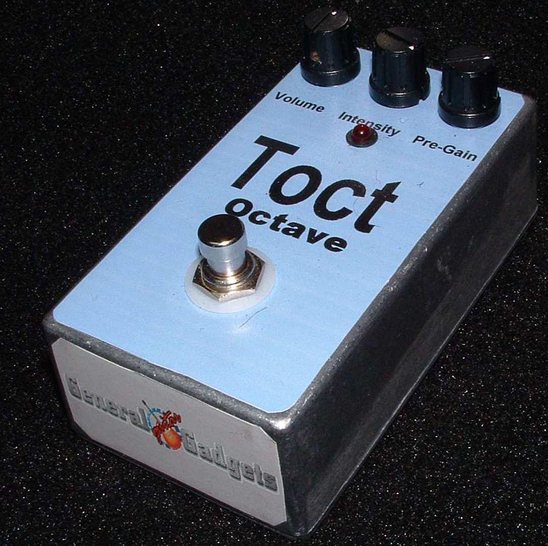
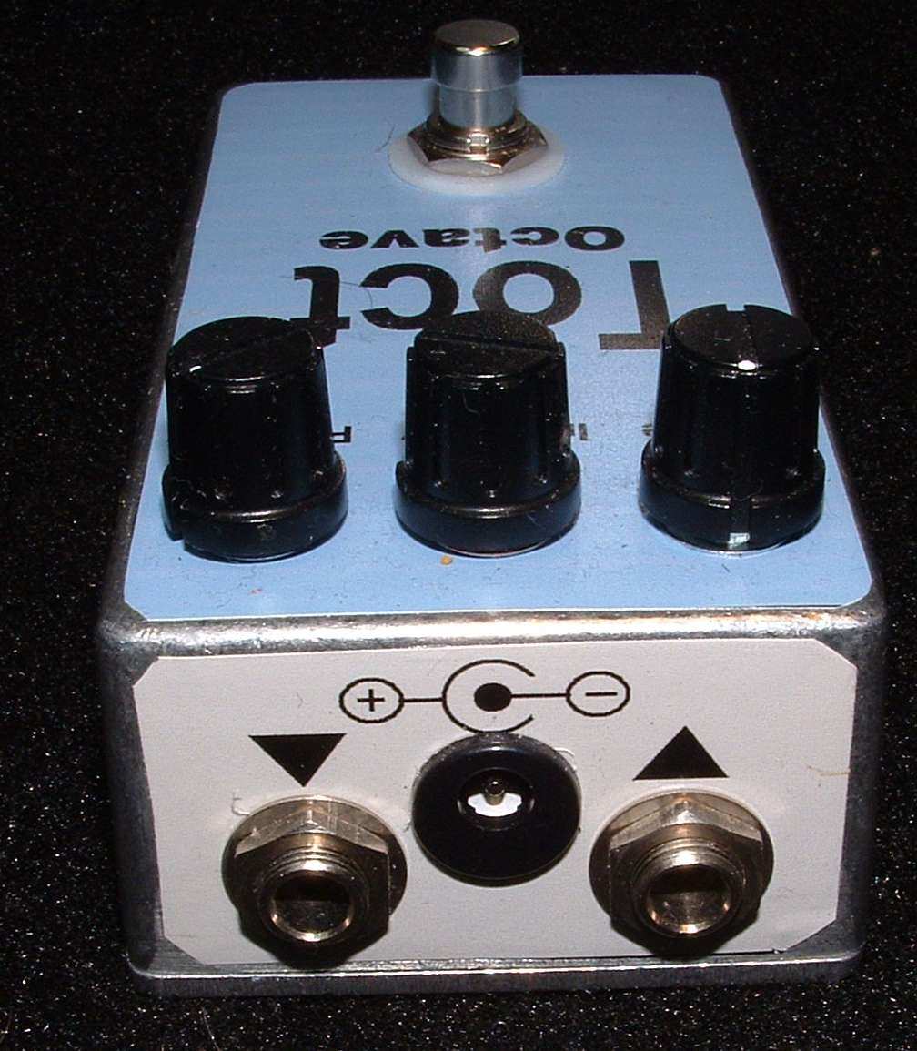
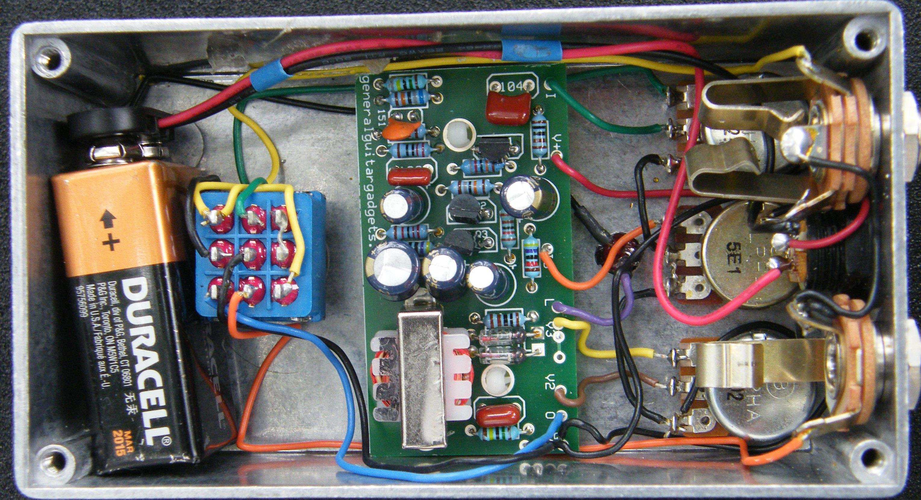
built without the PreGain control, just bypass the control and hook the input form the bypass switch directly into the PCB input pad. Also, if you want to build to original specifications, it can be done on this PCB as well. If you want to add the "fuzz" switch to cut the octave sound and have intense fuzz, use the extra pads above the diodes. One wire from one pad to one lug of a SPST toggle switch and the other wire from the other pad to the other lug on the toggle switch. Some of the PCBs may have a built in jumper there, just cut it with an exacto knife. Here's an inside view of the unit we built to show some construction details. Note that the photo shows an older version of the PCB, where Q1 is reversed and there is a built in jumper on the pads above the diodes. Your PCB may not be the same.
This is a fun effect, works well with other effects. Have fun, comments and questions are welcome and can be sent to [email protected]
Here is a chart of voltages taken at the transistor pins. This information can be used to help you find and fix problems if your TOCT doesn't work when you test it. Component
Location
9 volt supply Q1
Q2
Q3
Voltage
9.4
Collector
4.3
Base
3.6
Emitter
3.0
Collector
9.4
Base
2.6
Emitter
2.0
Collector
5.0
Base
2.3
Emitter
1.7
ycho*
Version 2016April14 · Copyright 2014 JD Sleep · Permission refused for posting/serving this file from any site other than www.generalguitargadgets.com · Trademarks are property of their owners
This is a replica of the octave stompbox we cannot mention by name referred to as TOCT in these documents. This Octave/Fuzz is extreme by most standards. Thanks to Fuzz Central for some of the information to make this a Negative-Ground circuit. The transistor selection can make some difference in the sound, but it is not critically important to getting a good sound. We have added a PreGain feature on this project since we noticed that the Octave sound is hard to achieve without tuning down the input some. For full out insanity, leave the PreGain and Intensity controls on full. Turn down both PreGain and Intensity to get good Hendrix type Octave sounds. There is an option for a toggle switch to select between Fuzz and Octave, but we built this one without since we wanted a straight up Octave box. With Intensity and PreGain on full, the Octave is somewhat "lost in the storm", with sounds of very, very intense fuzz. You should be able to get lots of controlled feedback and swells on most amps even at moderate and low volume levels. Positioning of Q1. There is a boutique version of this circuit that has the Q1 transistor reversed (emitter to collector reversed). The circuit works similar and has a slightly different sound when you install Q1 like this. The first version of our PCB had the transistor reversed on the screen print on the PCB and the older diagrams had it like this. We decided to change it back to the original way. Follow the diagrams for the original placement or for a modification, you can reverse Q1 and see if you like it. This is a relatively simple effect to build. Use the project documents provided, starting with the General Build Instructions. Note that if you prefer, it can easily be
built without the PreGain control, just bypass the control and hook the input form the bypass switch directly into the PCB input pad. Also, if you want to build to original specifications, it can be done on this PCB as well. If you want to add the "fuzz" switch to cut the octave sound and have intense fuzz, use the extra pads above the diodes. One wire from one pad to one lug of a SPST toggle switch and the other wire from the other pad to the other lug on the toggle switch. Some of the PCBs may have a built in jumper there, just cut it with an exacto knife. Here's an inside view of the unit we built to show some construction details. Note that the photo shows an older version of the PCB, where Q1 is reversed and there is a built in jumper on the pads above the diodes. Your PCB may not be the same.
This is a fun effect, works well with other effects. Have fun, comments and questions are welcome and can be sent to [email protected]
Here is a chart of voltages taken at the transistor pins. This information can be used to help you find and fix problems if your TOCT doesn't work when you test it. Component
Location
9 volt supply Q1
Q2
Q3
Voltage
9.4
Collector
4.3
Base
3.6
Emitter
3.0
Collector
9.4
Base
2.6
Emitter
2.0
Collector
5.0
Base
2.3
Emitter
1.7
More about this project
Notes, sounds and related links

JD's Comments:
This project was altered to be an NPN circuit which means that you can use this box on the same power supply as most other pedals. I've built both the PNP and NPN and the sound is the same. R1, R14 and C7 are optional. If C7 is not used you need to use a jumper in its place. The standard octave sounds seems to come out better if you turn the intensity down some. With the controls on full blast you get some great swells and wild sustain.
Ready to build? We have the kit.
Buy a TOCT Complete Kit. Includes all the parts and materials you need to build one, all for about the price you would pay for a PCB and parts. 
Would you like a Ready to Solder Circuit Board for this project? Note: If you buy the kit, the Ready-to-Solder Printed Circuit Board (RTS PCB) is included in the kit. You do not need to purchase this Ready to Solder Circuit Printed Board if you buy the kit.