
Project files
Everything you need to build it
Tone Machine™ Ready-For-Transfer Printed Circuit Board Layout - For use only if you are a complete DIY person who wants to etch and drill your own PCB. Otherwise, we recommend you ignore this PCB mask and buy the Ready-to-Solder Printed Circuit Board or Complete Kit.
Parts layout
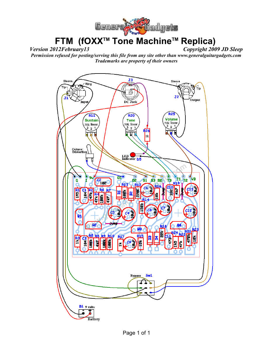
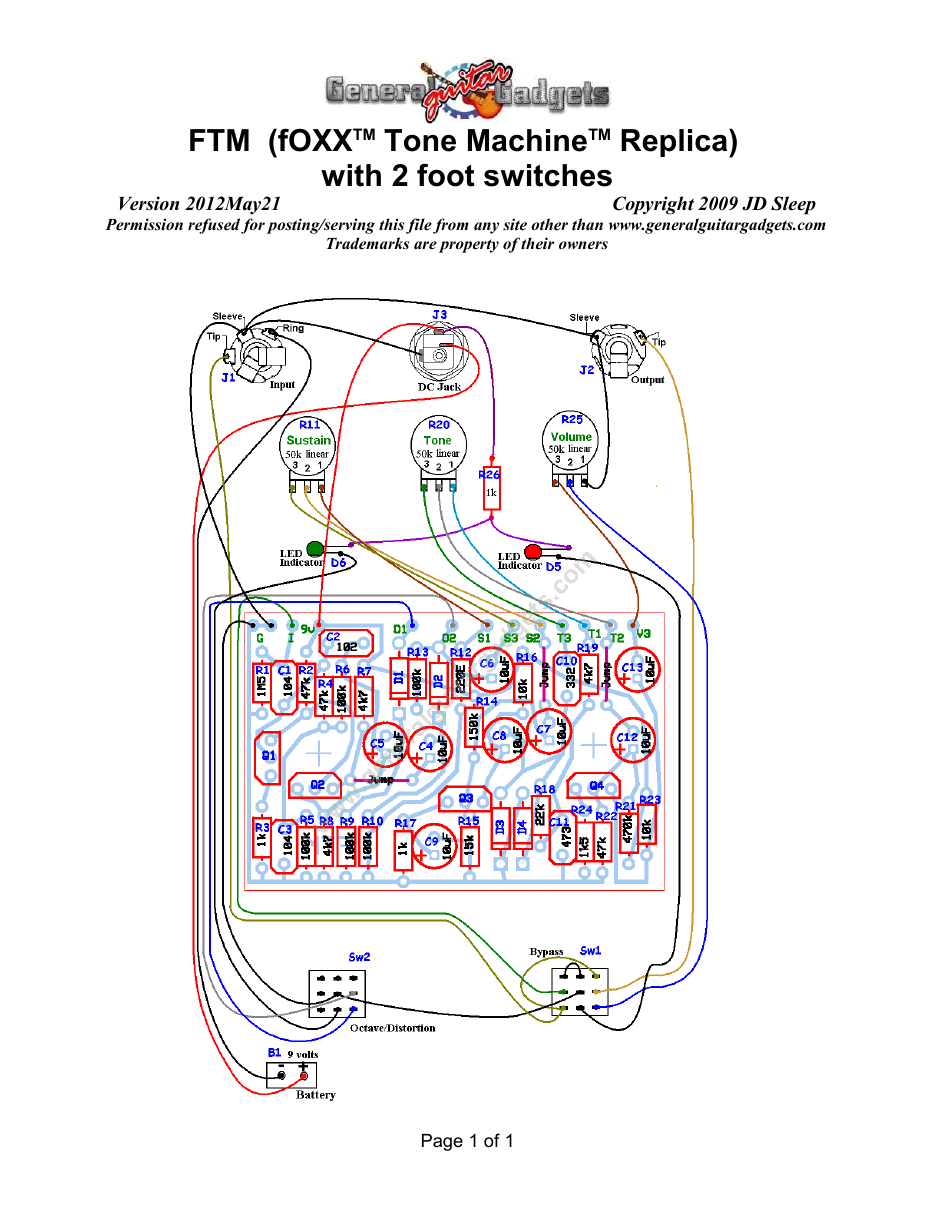
Parts Layout / Wiring Diagram
What you will need
Bill of Materials
Version 2012May21 · Copyright 2009 JD Sleep · Permission refused for posting/serving this file from any site other than www.generalguitargadgets.com · Trademarks are property of their owners
Resistors
| Resistor ID | Value | 3-band Marking | 4-band Marking |
|---|---|---|---|
| R1 | 1M5 (1.5M) | brown-green-green | brown-green-black-yellow |
| R2 | 47k | yellow-violet-orange | yellow-violet-black-red |
| R3 | 1k | brown-black-red | brown-black-black-brown |
| R4 | 47k | yellow-violet-orange | yellow-violet-black-red |
| R5 | 100k | brown-black-yellow | brown-black-black-orange |
| R6 | 100k | brown-black-yellow | brown-black-black-orange |
| R7 | 4k7 (4.7k) | yellow-violet-red | yellow-violet-black-brown |
| R8 | 4k7 (4.7k) | yellow-violet-red | yellow-violet-black-brown |
| R9 | 100k | brown-black-yellow | brown-black-black-orange |
| R10 | 100k | brown-black-yellow | brown-black-black-orange |
| R11 (Sustain Control | 50k Linear Potentiometer | ||
| R12 | 220 ohm | red-red-brown | red-red-black-black |
| R13 | 100k | brown-black-yellow | brown-black-black-orange |
| R14 | 150k | brown-green-yellow | brown-green-black-orange |
| R15 | 15k | brown-green-orange | brown-green-black-red |
| R16 | 10k | brown-black-orange | brown-black-black-red |
| R17 | 1k | brown-black-red | brown-black-black-brown |
| R18 | 22k | red-red-orange | red-red-black-red |
| R19 | 4k7 (4.7k) | yellow-violet-red | yellow-violet-black-brown |
| R20 (Tone Control) | 50k Linear Potentiometer | ||
| R21 | 470k | yellow-violet-yellow | yellow-violet-black-orange |
| R22 | 47k | yellow-violet-orange | yellow-violet-black-red |
| R23 | 10k | brown-black-orange | brown-black-black-red |
| R24 | 1k5 (1.5k) | brown-green-red | brown-green-black-brown |
| R25 (Volume Control) | 50k Linear Potentiometer | ||
| R26 | 1k | brown-black-red | brown-black-black-brown |
Capacitors
| Capacitor ID | Value | Type | Possible Marking |
|---|---|---|---|
| C1 | 0.1µF | Film or Ceramic | 104 |
| C2 | 0.001µF | Film or Ceramic | 102 |
| C3 | 0.1µF | Film or Ceramic | 104 |
| C4 | 10µF | Aluminum Electrolytic | 10µF |
| C5 | 10µF | Aluminum Electrolytic | 10µF |
| C6 | 10µF | Aluminum Electrolytic | 10µF |
| C7 | 10µF | Aluminum Electrolytic | 10µF |
| C8 | 10µF | Aluminum Electrolytic | 10µF |
| C9 | 10µF | Aluminum Electrolytic | 10µF |
| C10 | 0.0033µF | Film or Ceramic | 332 |
| C11 | 0.047µF | Film or Ceramic | 473 |
| C12 | 10µF | Aluminum Electrolytic | 10µF |
| C13 | 10µF | Aluminum Electrolytic | 10µF |
Potentiometers
| Part ID | Value | Type |
|---|---|---|
| R11 - Sustain Control | 50k | Linear Taper |
| R20 - Tone Control | 50k | Linear Taper |
| R25 - Volume | 50k | Linear Taper |
Other
| Part ID | Part Name |
|---|---|
| Q1, Q2, Q3, Q4 | 2N3904 or other NPN Bipolar Transistors |
| D1, D2, D3, D4 | 1N34A Germanium Diodes |
| D5 | LED |
| Sw2 | On-off Mini Toggle Switch |
| J1 | Stereo quarter-inch jack |
| J2 | Mono quarter-inch jack |
| J3 | DC Jack |
| B1 | 9 volt battery (not included in the Kit) |
| Sw1 | Heavy Duty 3PDT foot switch 9v battery snap, Printed Circuit Board, 24 gauge stranded wire, Enclosure, Knobs |
How to build it
Instructions
Version 2012May21 · Copyright 2007 JD Sleep · Permission refused for posting/serving this file from any site other than www.generalguitargadgets.com · Trademarks are property of their owners
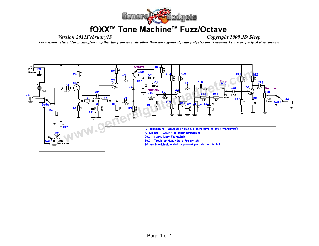
This is a replica of the fOXXTM Tone MachineTM referred to as FTM in these documents. This pedal has a great fuzz sound and Octave sound as well. Use the project documents provided, starting with the General Build Instructions. Refer to the FTM Project for reference. Comments and questions are welcome and can be sent to [email protected] Here is a chart of voltages taken at the transistor pins. This information can be used to help you find and fix problems if your FTM doesn't work when you test it.
Component
Location
9 volt power supply Q1
Q2
Q3
Q4
Voltage
9.26
Collector
2.2
Base
0.73
Emitter
0.16
Collector
7.5
Base
2.2
Emitter
1.6
Collector
7.28
Base
0.78
Emitter
0.21
Collector
7.63
Emitter
0.84
Base
0.26

More about this project
Notes, sounds and related links

JD's Comments:
This is one of my favorite of the old-time fuzz tones (1965-1975 era). I love the long sustain capabilities. I used the "Tone Machine™" section from my original fOXX Fuzz/Wah/Volume pedal as a guide for building this one (sound comparison). The circuit is the same as the Tone Machine™. The original has orange drop caps and other large size film caps for the non-electrolytic caps.
I tried lots of different transistors, 2N2222A, 2N3904, PN3565 and 2N5088. I could not hear any difference in the sound with any of these different transistors. My original has BC237B transistors. If you want to use sockets on the transistors, the layout is designed to use SIP sockets for the transistor sockets.
Ready to build? We have the kit.
Buy a FTM Complete Kit. Includes all the parts and materials you need to build one, all for about the price you would pay for a PCB and parts.

Would you like a Ready to Solder Circuit Board for this project? Note: If you buy the kit, the Ready-to-Solder Printed Circuit Board (RTS PCB) is included in the kit. You do not need to purchase this Ready to Solder Circuit Printed Board if you buy the kit.