
Project · Fuzz Tones
Univox™ Super Fuzz™
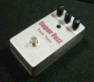
This is a replica of the Univox™ Super-Fuzz, the 1968 octave fuzz behind Pete Townshend's Live at Leeds tone: six transistors, two germanium diodes and the scooped-tone switch. The complete kit is $55 with every part and a balance trimmer that removes the need to match transistors; the free schematic, wiring diagram and a modification sheet are below.
One of the most famed fuzztones of all time, and that's easy to understand when you hear it. A complete kit is available or use the RTS-PCB to build this fuzz.
The story
About the circuit
The Super-Fuzz was built in Japan by Shin-ei™ (as the FY-6) and sold in the United States under the Univox™ name from 1968; in the UK the same circuit was usually badged Shaftesbury Duo Fuzz. It is a six-transistor circuit: an input stage, a phase splitter driving a differential pair that full-wave rectifies the signal to create an upper octave, two germanium diodes for hard clipping, and a two-position tone switch that either leaves the signal flat or scoops the midrange. Pete Townshend used it throughout the Live at Leeds era, and it later became a staple of grunge and stoner rock. Original units need matched transistors in the differential pair for the octave to come through cleanly.
This project at GGG
We added the Super-Fuzz in 2014, and the one practical change we made was to put a balance trimmer on the differential pair. Matching transistors by hand is the part of this build that used to put people off; with the trimmer you set it by ear for the strongest octave and move on. The modification sheet covers tone-switch and gain tweaks, and the board fits a 125B enclosure. It is the most popular octave fuzz on the site.
Project files
Everything you need to build it
Univox™ Super Fuzz™ Ready-For-Transfer to Printed Circuit Board - For use only if you are a complete DIY person who wants to etch and drill your own PCB. Otherwise, we recommend you ignore this PCB mask and buy the Ready-to-Solder Printed Circuit Board or Complete Kit.
Schematic
Schematic
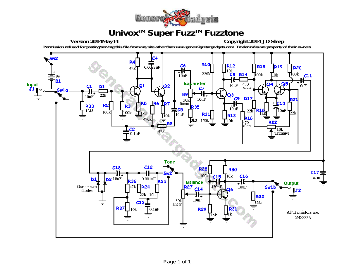
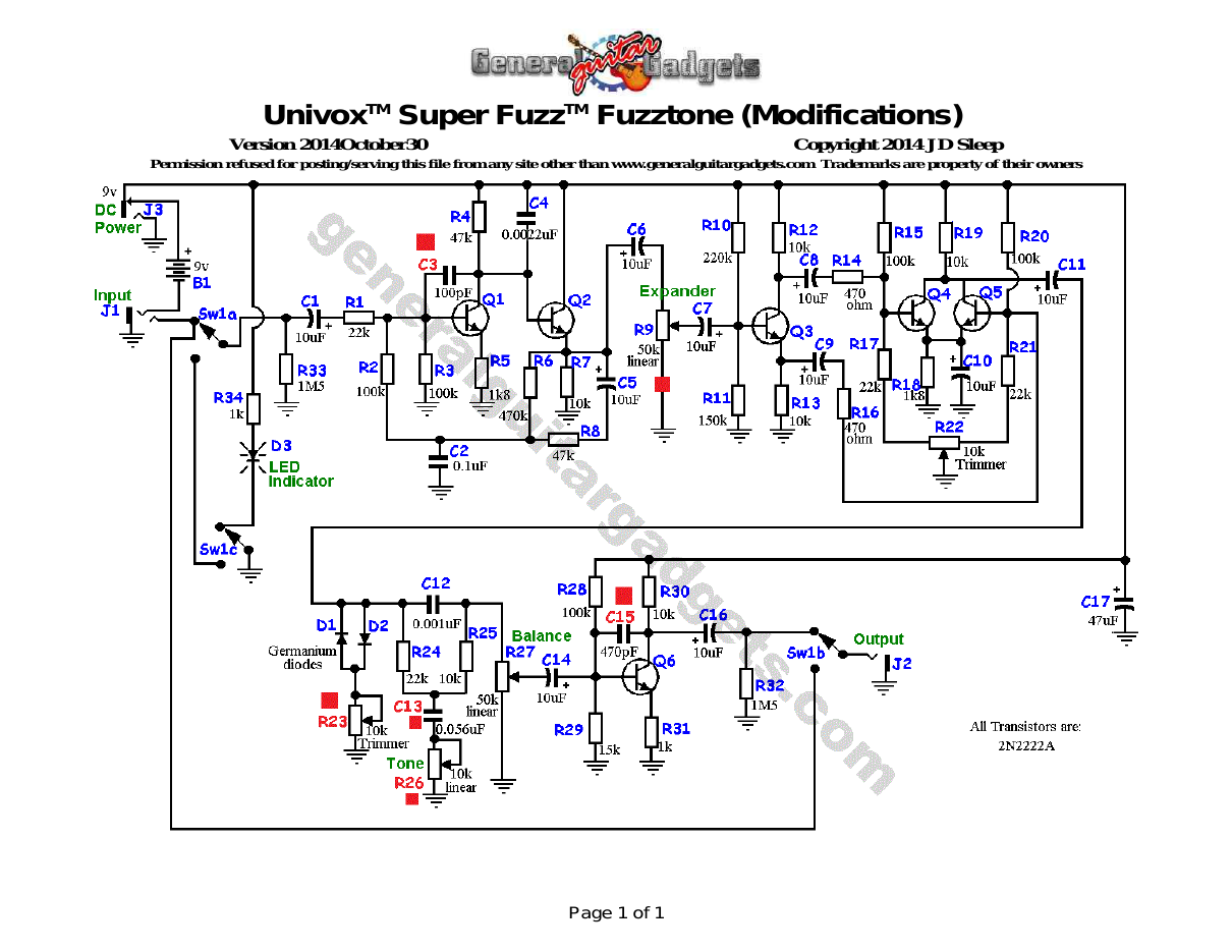
Parts layout
Parts Layout / Wiring Diagram
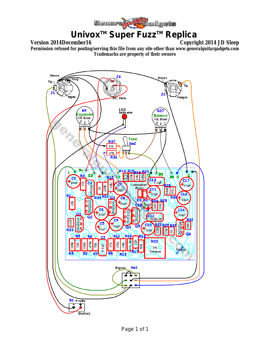
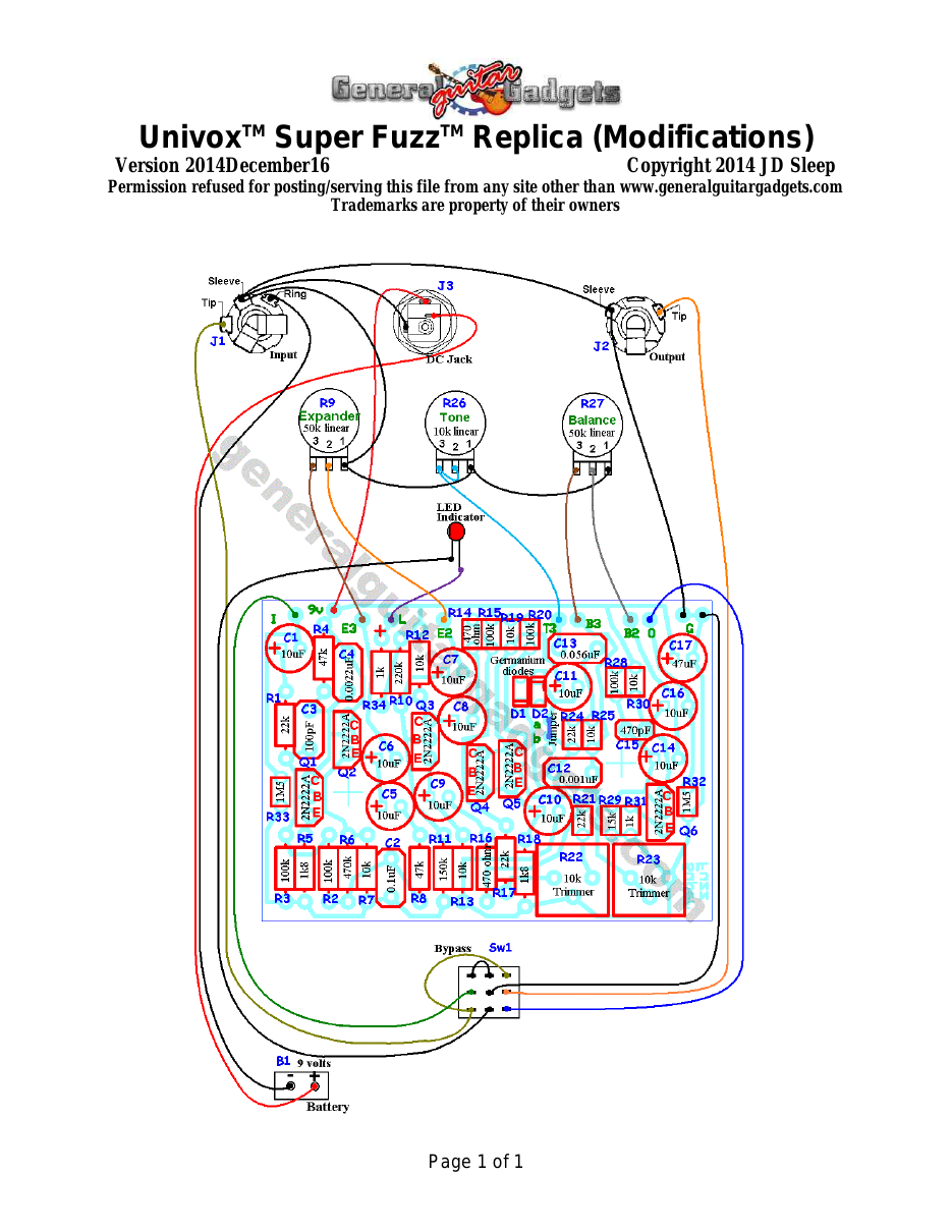
What you will need
Bill of Materials
Version 2014June20 · Copyright 2014JD Sleep · Permission refused for posting/serving this file from any site other than www.generalguitargadgets.com · Trademarks are property of their owners
Resistors
| Resistor ID | Value | 3-band Marking | 4-band Marking |
|---|---|---|---|
| R1 | 22k | red-red-orange | red-red-black-red |
| R2 | 100k | brown-black-yellow | brown-black-black-orange |
| R3 | 100k | brown-black-yellow | brown-black-black-orange |
| R4 | 47k | yellow-violet-orange | yellow-violet-black-red |
| R5 | 1k8 (1.8k) | brown-gray-red | brown-gray-black-brown |
| R6 | 470k | yellow-violet-yellow | yellow-violet-black-orange |
| R7 | 10k | brown-black-orange | brown-black-black-red |
| R8 | 47k | yellow-violet-orange | yellow-violet-black-red |
| R9 (Expander Control Potentiometer) | 50k Linear | ||
| R10 | 220k | red-red-yellow | red-red-black-orange |
| R11 | 150k | brown-green-yellow | brown-green-black-orange |
| R12 | 10k | brown-black-orange | brown-black-black-red |
| R13 | 10k | brown-black-orange | brown-black-black-red |
| R14 | 470 ohm | yellow-violet-brown | yellow-violet-black-black |
| R15 | 100k | brown-black-yellow | brown-black-black-orange |
| R16 | 470 ohm | yellow-violet-brown | yellow-violet-black-black |
| R17 | 22k | red-red-orange | red-red-black-red |
| R18 | 1k8 (1.8k) | brown-gray-red | brown-gray-black-brown |
| R19 | 10k | brown-black-orange | brown-black-black-red |
| R20 | 100k | brown-black-yellow | brown-black-black-orange |
| R21 | 22k | red-red-orange | red-red-black-red |
| R22 (Balance Trimmer) | 10k Trimmer Potentiometer | ||
| R23 (Clipping | 10k Trimmer Potentiometer | ||
| Trimmer) | (optional) | ||
| R24 | 22k | red-red-orange | red-red-black-red |
| R25 | 10k | brown-black-orange | brown-black-black-red |
| R26 (Tone Control) | 10k Linear Potentiometer | ||
| R27(Balance Control) | 50k Linear Potentiometer | ||
| R28 | 100k | brown-black-yellow | brown-black-black-orange |
| R29 | 15k | brown-green-orange | brown-green-black-red |
| R30 | 10k | brown-black-orange | brown-black-black-red |
| R31 | 1k | brown-black-red | brown-black-black-brown |
| R32 | 1M5 (1.5M) | brown-green-green | brown-green-black-yellow |
| R33 | 1M5 (1.5M) | brown-green-green | brown-green-black-yellow |
| R34 | 1k | brown-black-red | brown-black-black-brown |
Capacitors
| Capacitor ID | Value | Type | Possible Marking |
|---|---|---|---|
| C1 | 10µF | Aluminum Electrolytic | 10µF |
| C2 | 0.1µF | Film or Ceramic | 104 |
| C3 | None | ||
| C4 | 0.0022µF | Film or Ceramic | 222 |
| C5 | 10µF | Aluminum Electrolytic | 10µF |
| C6 | 10µF | Aluminum Electrolytic | 10µF |
| C7 | 10µF | Aluminum Electrolytic | 10µF |
| C8 | 10µF | Aluminum Electrolytic | 10µF |
| C9 | 10µF | Aluminum Electrolytic | 10µF |
| C10 | 10µF | Aluminum Electrolytic | 10µF |
| C11 | 10µF | Aluminum Electrolytic | 10µF |
| C12 | 0.001µF | Film or Ceramic | 102 |
| C13 | 0.1µF | Film or Ceramic | 104 |
| C14 | 10µF | Aluminum Electrolytic | 10µF |
| C15 | None | ||
| C16 | 10µF | Aluminum Electrolytic | 10µF |
| C17 | 47µF | Aluminum Electrolytic | 47µF |
| C18 | 10µF | Aluminum Electrolytic | 10µF |
Potentiometers
| Part ID | Value | Type |
|---|---|---|
| R9 - Expander Control | 50k | Linear Taper |
| R22 – Octave Balance Trimmer | 10k | |
| R23 - Clipping Trimmer | 10k | |
| R26 - Tone Control | 10k | Linear Taper |
| R27 – Balance Control | 50k | Linear Taper |
Other
| Part ID | Part Name |
|---|---|
| D1 | 1N270 (or other Germanium diode) |
| D2 | 1N270 (or other Germanium diode) |
| D3 | LED |
| Q1 | 2N2222A bipolar junction transistor |
| Q2 | 2N2222A bipolar junction transistor |
| Q3 | 2N2222A bipolar junction transistor |
| Q4 | 2N2222A bipolar junction transistor |
| Q5 | 2N2222A bipolar junction transistor |
| Q6 | 2N2222A bipolar junction transistor |
| J1 | Stereo quarter-inch jack |
| J2 | Mono quarter-inch jack |
| J3 | DC Jack |
| B1 | 9 volt battery (not included in the Kit) |
| Sw1 | Heavy Duty 3PDT foot switch 9v battery snap, Printed Circuit Board, 24 gauge stranded wire, Enclosure, Knobs |
How to build it
Instructions
Version 2014June20 · Copyright 2014 JD Sleep · Permission refused for posting/serving this file from any site other than www.generalguitargadgets.com · Trademarks are property of their owners
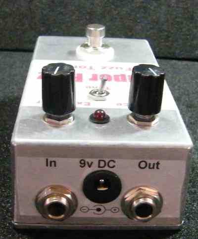
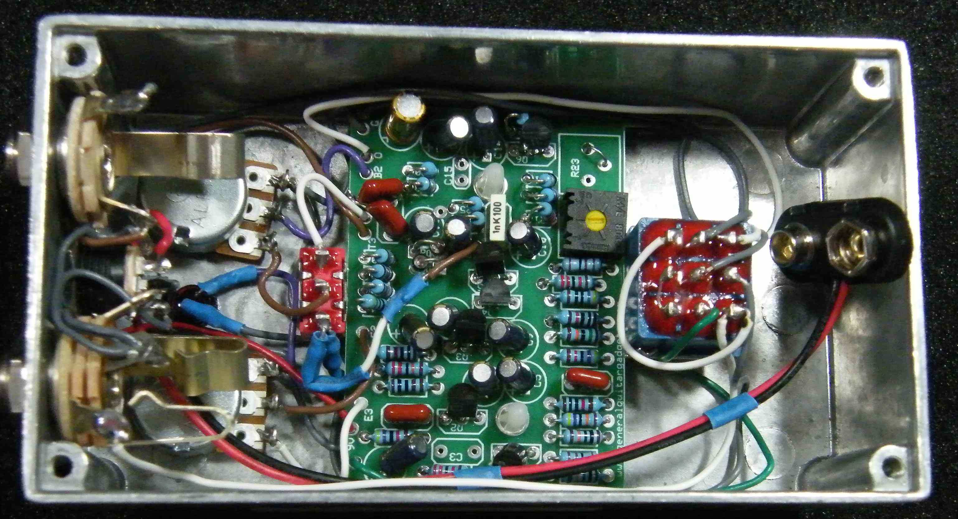
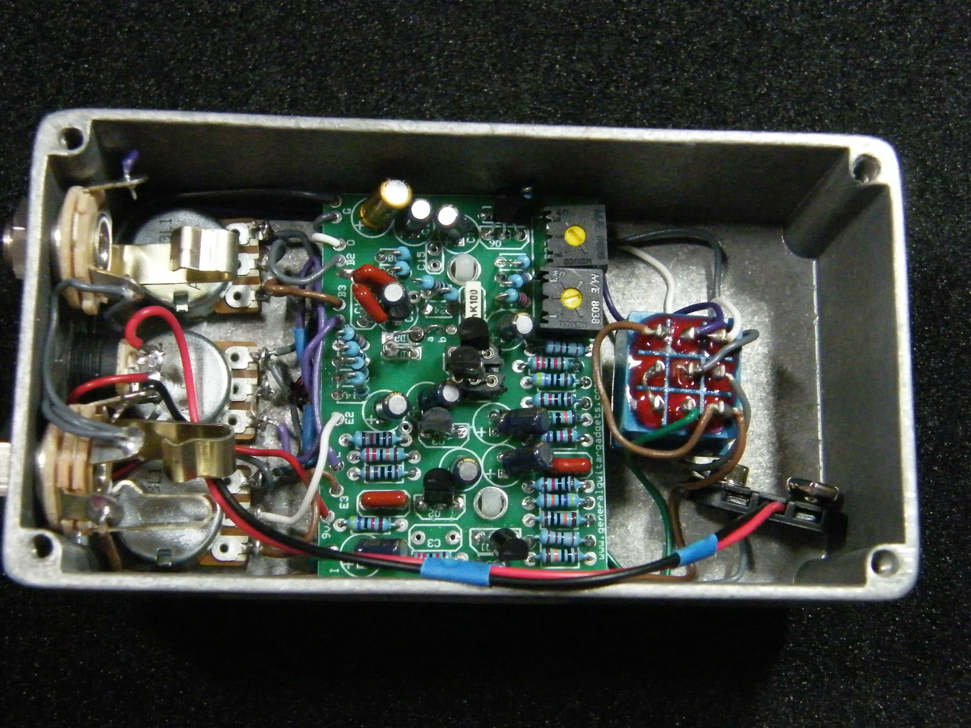
This is a replica of the UnivoxTM Super Fuzz™. The PCB for this project has room for several modifications, including replacing the tone switch with a tone potentiometer, as most modern stompboxes have. These instructions describe how to build it stock as the originals that sold, new, in the 1970's, with a tone toggle switch (originally a slider switch) and no other modifications. Be sure to check out the PDF file with modifications information and decide if you want to build it stock or with modifications. Please Note: The 2N2222A transistors in the kit have a pin designation opposite of most transistors that we use. So The transistors are mounted opposite of what the screen-print on the PCB indicates. Follow the General Instructions and the Layout/Wiring Diagram. There are some component spots on the PCB that will be empty since they are for modifications. These are C3, C15 and R23 (trimmer). Also there are a few components that will need to be mounted on the switch and Expander potentiometer. You should solder tack these components to the switch or potentiometer and to the connecting wires. Also, make sure you put a little jumper across the R23 trimmer spot as shown in the diagram and in the photo below. Here's an inside view of the unit we built to give you a general idea of how it looks

when completed.
Here is a chart of voltages taken at the transistor pins. Use these voltages as a guideline. You won't get these exact readings, but they should be somewhere in the area.
Component
Location
9 volt power supply Q1
Q2
Voltage
9.5v
Collector
5.6v
Base
0.8v
Emitter
0.2v
Collector
9.5v
Base
5.6v
Q3
Q4
Q5
Q6
Emitter
5.0v
Collector
6.4v
Base
3.7v
Emitter
3.0v
Collector
2.1v
Base
1.9v
Emitter
1.3v
Collector
2.1v
Base
1.9v
Emitter
1.3v
Collector
4.0v
Base
1.2v
Emitter
0.6v
Questions
Frequently asked questions
What does the tone switch do?
Up is the stock notched sound with the mids cut; down is flat and fuller. The mod sheet shows how to replace it with a tone pot.
Where does the octave come from?
Q4 and Q5 form a phase-splitter that doubles the signal; play above the 12th fret with the neck pickup and the octave-up jumps out.
Do I need matched transistors?
No. The R22 balance trimmer sets Q4/Q5 for the strongest octave, so the six 2N2222As in the kit work as supplied.
How hard is the build?
Moderate: about 50 parts and a transistor pinout that is the reverse of the board's silkscreen (the instructions show it). Build a two-transistor fuzz first if this is your first pedal.
Make it your own
Modification Instructions
Version 2014June · Copyright 2014 JD Sleep · Permission refused for posting/serving this file from any site other than www.generalguitargadgets.com · Trademarks are property of their owners
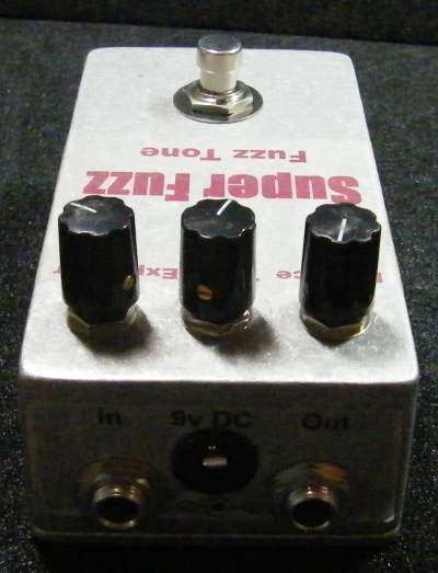
This is a replica of the UnivoxTM Super Fuzz™, and these are some modifications that you can do with yours when you build it. For these mods refer to the Modification Schematic and Layout PDF files that are on the project page on the site. Little red boxes on the schematic file indicate all the modifications listed in this file. Modification 1 The original Super Fuzz™ had a Tone (notch) switch to switch between the popular nasally, raspy fuzz sound of the sixties to a more full bodied fuzz like you would hear in an old song by “The Who” (maybe). The first mod is to replace the switch with a more modern tone control potentiometer control. You can still get the two sounds of the switch, plus you get all the sounds in between. Refer to the Mods Schematic and Layout Diagrams. Use the wiring from these diagrams and use the tone potentiometer (R26) instead of the switch (Sw2). Note that you will need an enclosure with a different drilling configuration to do this modification. Modification 2 This modification adds Trimmer R23 (or can be a panel mount potentiometer) to give some control on the distortion clipping. Modification 3 This modification adds a couple of small value caps across the transistor stages to smooth things out a bit. This is adding C3 and/or C15. You'll have to try this to see if you like this or not. The values can vary depending on the sound you are looking for. Suggested values are shown in the diagrams, but you may find other values more
- desirable for your sound.
- Modification 4
- Removing R35 from the Expander potentiometer lug 1 to ground. R35 is sort of
- unnecessary and you can get the full range of R9 if you leave it off.
- Other Notes
- R33 is added to help reduce the possibility of audible bypass switch clicking. It
- can be left out, but is a good addition in our opinion.
- Some versions did not have R22 trimmer to balance the Q4 and Q5 transistors.
- We have included it since it lets you be less concerned about matching those
- transistors and to tune in the sound to your liking with the trimmer.
- The modifications should not significantly influence the voltage readings you
- get at the transistor pins, so even with the mods, you should still get about the
- same readings listed in the instructions file.
- Here's an inside view of the unit we built to give you a general idea of how it looks
- when completed. This one does not include the C3 and C15 caps, but has the
- clipping trimmer and the tone potentiometer.
More about this project
Notes, sounds and related links

Ready to build? We have the kit.
Buy a Super Fuzz™ Complete Kit. Includes all the parts and materials you need to build one, all for about the price you would pay for a PCB and parts.

Would you like a Ready to Solder Circuit Board for this project?