
Project · Fuzz Tones
Mosrite™ Fuzzrite™ Replica
Raw and awesome! This Fuzz Tone has a very good "Spirit In The Sky" fuzz sound. It is reported to be the Fuzz Tone used by Eric Brann of Iron Butterfly in the classic song "In-A-Gadda-Da Vida". It was apparently also a favorite fuzz tone used by many in the "San Francisco Psychedelic Music Scene of the 1960's". A complete kit is available or use the SECF RTS-PCB to build this fuzz. Any Trademarks mentioned here belong to their owners and NOT General Guitar Gadgets.
The story
About the circuit
Mosrite™ of California, Semie Moseley's guitar company in Bakersfield, released the Fuzzrite™ in 1966. Designed by Ed Sanner, it was one of the first American-made fuzz pedals and used a two-transistor circuit quite different from the Fuzz Face™: the "fuzz" (or "depth") control blends the output of the two stages rather than setting gain, which is why it behaves more like a tone control with a volume jump at the end of its travel. Early units were germanium, later ones silicon. The buzzy, raspy sound became a fixture of 1960s West Coast garage and psychedelic rock; Iron Butterfly's "In-A-Gadda-Da-Vida" is the usual reference.
This project at GGG
We added the Fuzzrite™ in 2009, when we designed the SECF board to cover several of the simple '60s fuzzes on one PCB. That is why a few component positions stay empty on this build; the layout shows exactly which. It uses ordinary low-gain silicon NPN transistors (2N3904, 2N4401, BC54x), it is one of the easier fuzzes on the site to build, and the instructions include the voltages we measured on our own unit for anyone who needs to troubleshoot. The kit ships with everything for a 125B enclosure.
Project files
Everything you need to build it
Mosrite™ Fuzzrite™ (SECF) Ready-For-Transfer Printed Circuit Board Layout
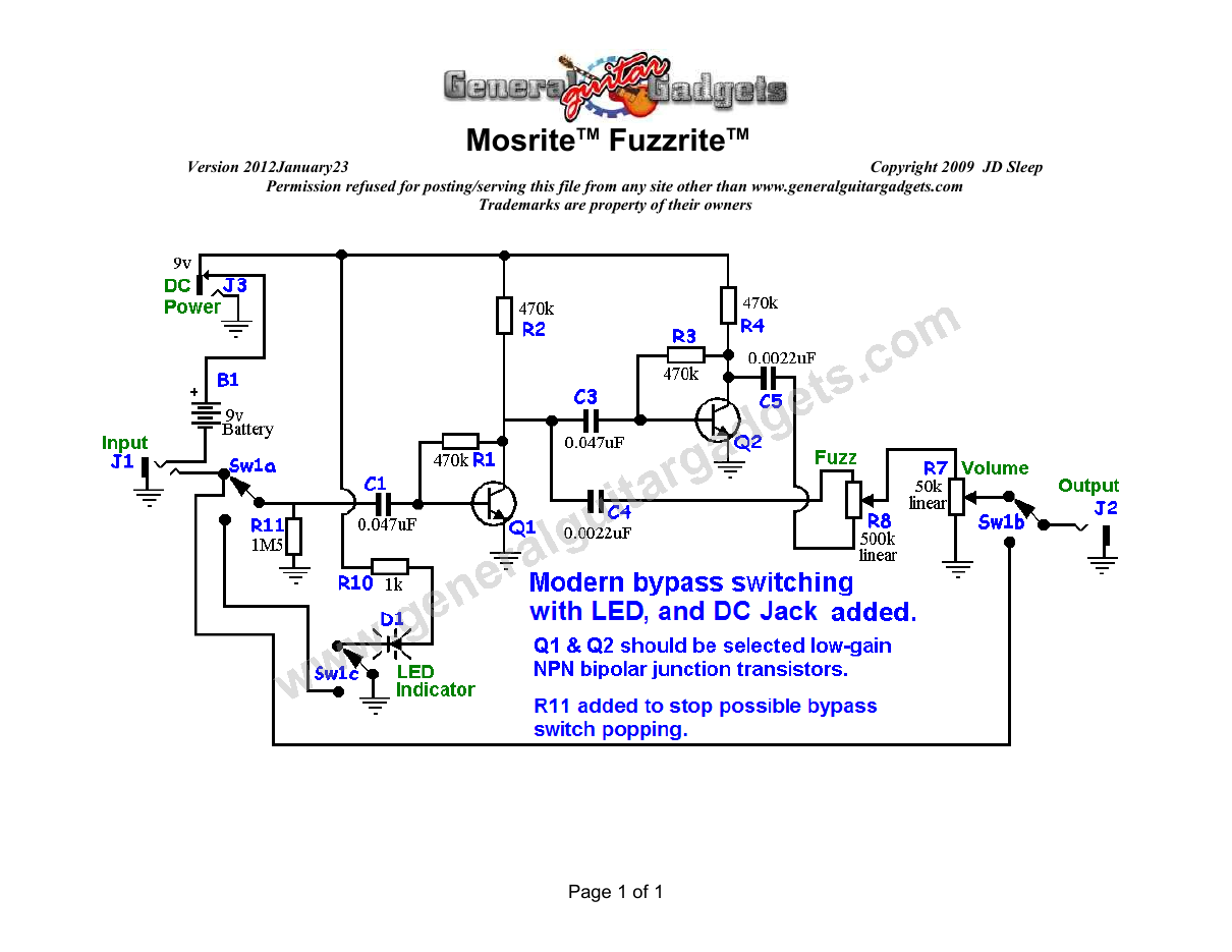
Parts layout
Parts Layout / Wiring Diagram
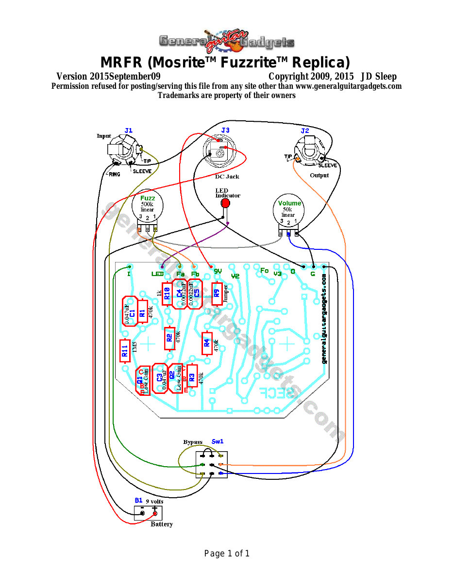
What you will need
Bill of Materials
Version 2012November12 · Copyright 2009 JD Sleep · Permission refused for posting/serving this file from any site other than www.generalguitargadgets.com · Trademarks are property of their owners
Resistors
| Resistor ID | Value | 3-band Marking | 4-band Marking |
|---|---|---|---|
| R1 | 470k | yellow-violet-yellow | yellow-violet-black-orange |
| R2 | 470k | yellow-violet-yellow | yellow-violet-black-orange |
| R3 | 470k | yellow-violet-yellow | yellow-violet-black-orange |
| R4 | 470k | yellow-violet-yellow | yellow-violet-black-orange |
| R5 | None | ||
| R6 | None | ||
| R9 | 0 ohm or jumper wire | black | black |
| R10 | 1k | brown-black-red | brown-black-black-brown |
| R11(Optional) | 1M5 | brown-green-green | brown-green-black-yellow |
| R12 | None | ||
| R13 | None | ||
| R14 | None | ||
| R15 | None | ||
| R16 | None |
Capacitors
| Capacitor ID | Value | Type | Possible Marking |
|---|---|---|---|
| C1 | 0.047µF | Film or Ceramic | 473 |
| C2 | None | ||
| C3 | 0.047µF | Film | 473 |
| C4 | 0.0022µF | Film | 222 |
| C5 | 0.0022µF | Film | 222 |
| C6 | None | ||
| C7 | None | ||
| C8 | None | ||
| C9 | None | ||
| C10 | None | ||
| C11 | None |
Potentiometers
| Part ID | Value | Type |
|---|---|---|
| R7 - Volume Control | 50k | Linear Taper |
| R8 - Fuzz Control | 500k | Linear Taper |
Other
| Part ID | Part Name |
|---|---|
| Q1 | low-gain NPN bipolar junction transistor |
| Q2 | low-gain NPN bipolar junction transistor |
| Q3 | None |
| D1 | None |
| J1 | Stereo quarter-inch jack |
| J2 | Mono quarter-inch jack |
| J3 | DC Jack |
| B1 | 9 volt battery (not included in the Kit) |
| Sw1 Examples of low-gain NPN bipolar junction transistors: ● 2N3904 ● 2N4401 ● BC546A ● BC547A ● BC548A ● BC549A | Heavy Duty 3PDT foot switch 9v battery snap, Printed Circuit Board, 24 gauge stranded wire, Enclosure, Knobs |
How to build it
Instructions
Version 2015March24 · Copyright 2015 JD Sleep · Permission refused for posting/serving this file from any site other than www.generalguitargadgets.com · Trademarks are property of their owners
This is a replica of the MosriteTM FuzzriteTM referred to as MRFR in these documents. This is an excellent fuzztone and is easy to build. It is built on a “multifunction” PCB, meaning the PCB was designed for more than one fuzztone, so there will be some blank component spaces on the PCB when you are finished. That's okay, just populate the PCB as shown in the layout and wiring diagram. Use the General Instructions file to build the kit. Note that R9 needs a jumper installed. You can use a zero-ohm resistor or a piece of wire in the space marked R9. Note that the Fuzz control knob on this fuzztone has a bit of a strange rotation. It doesn't get more and more fuzz as you turn clock-wise as you would expect on the usual fuzztone. The rotation controls mostly the tone. There is a big volume boost at the end of the clockwise rotation. On the counter-clockwise rotation it has a "hump" where it gets less treble and then treble comes up somewhat again towards the end of the CCW rotation. The Kits may have “can” (TO18) transistors for Q1 and Q2. If so, use the diagrams below to determine the pin orientation of the transistors:
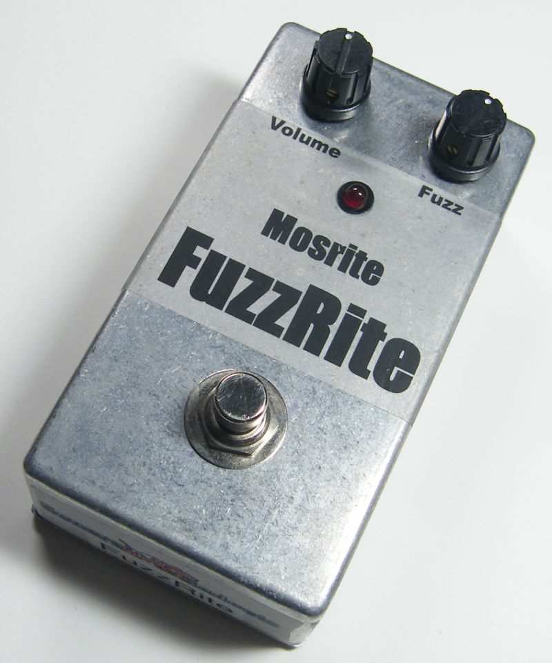
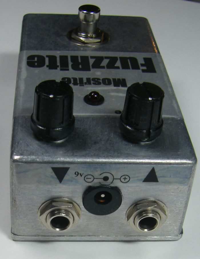
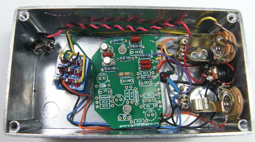
Here's an inside view of the unit we built to how it looks when assembled in a 125B enclosure.
This is a fun effect, works well with other effects. Have fun, comments and questions are welcome and can be sent to [email protected]
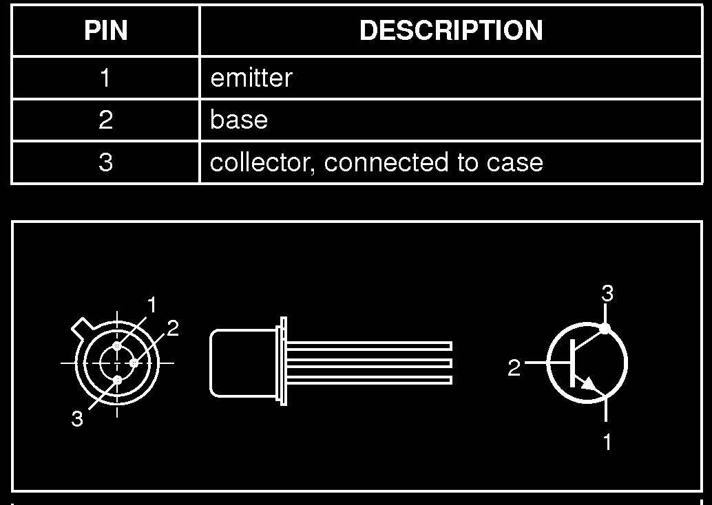
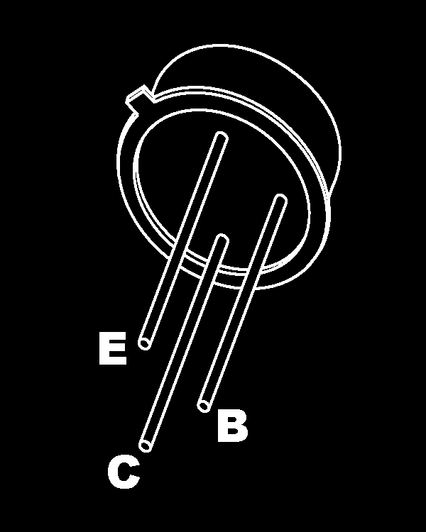
Here is a chart of voltages taken at the transistor pins. This information can be used to help you find and fix problems if your Fuzzrite™ doesn't work when you test it.
Component
Location
9 volt power supply Q1
Q2
Voltage
9.2v
Collector
0.77v
Base
0.63v
Emitter
0v
Collector
0.77v
Base
0.63v
Emitter
0v
More about this project
Notes, sounds and related links

Ready to build? We have the kit.
Buy a MRFR Complete Kit. Includes all the parts and materials you need to build one, all for about the price you would pay for a PCB and parts. 
Would you like a Ready to Solder Circuit Board for this project? Note: The PCB is Multi-Use and is labeled "SECF" Note: If you buy the kit, the Ready-to-Solder Printed Circuit Board (RTS PCB) is included in the kit. You do not need to purchase this Ready to Solder Circuit Printed Board if you buy the kit.