
Project · Fuzz Tones
Fuzz Face™
The FF5 is our Fuzz Face™ replica, the two-transistor fuzz Hendrix made famous, and its board builds five versions: the silicon and germanium Dallas Arbiter™ originals, two boutique late-60s and early-70s variants, and Joe Gagan's Easy Face with a blend control. The complete kit is $50 with low-gain silicon transistors, sockets and a bias trimmer; free schematics and wiring diagrams for every version are below.
This is the Fuzz Face™ project know as FF5, the "5" denotes that there are at least 5 different versions that you can build with this project. Here they are!
The story
About the circuit
Arbiter Electronics of London introduced the Fuzz Face™ in 1966. Ivor Arbiter is said to have taken the round enclosure from a microphone-stand base, and the knobs-and-switch "face" became the most recognisable pedal shape ever made. Electrically it is about as simple as a fuzz gets: two transistors in a feedback pair, a fuzz control and a volume control. The first units used PNP germanium transistors (commonly NKT275) and ran positive ground; by about 1968 production had moved to silicon BC108 and later BC183 transistors, which are brighter, more stable and higher gain. Jimi Hendrix used both. After Arbiter merged with Dallas Musical Industries the pedal was sold as the Dallas Arbiter™ Fuzz Face™, and it has been reissued many times since.
This project at GGG
The Fuzz Face™ was one of the first projects JD put up, back when this site was a free-hosted page called "Guitar Effects Projects." In those days the DIY community was posting plenty of reverse-engineered schematics of classic pedals but almost no layouts, so JD drew his own and shared them; the Fuzz Face™ layout was among the first. There were two versions then, the Fuzz Face™ and the '69, plus Joe Gagan's Easy Face next door. Over the years those grew into one board that builds at least five fuzzes, which is why we call the project FF5: the germanium and silicon Dallas Arbiter™ versions, a late-'60s and an early-'70s boutique variant, and the Easy Face with its blend control. Putting them on one board meant anyone could build the version they wanted, or build two and compare. The kit ships with a bias trimmer and sockets so you can tune the sound and swap transistors without unsoldering, and the instructions cover positive- and negative-ground builds and a charge-pump option for running PNP germanium on an ordinary negative-ground pedalboard. This is the page most new builders start on.
Project files
Everything you need to build it
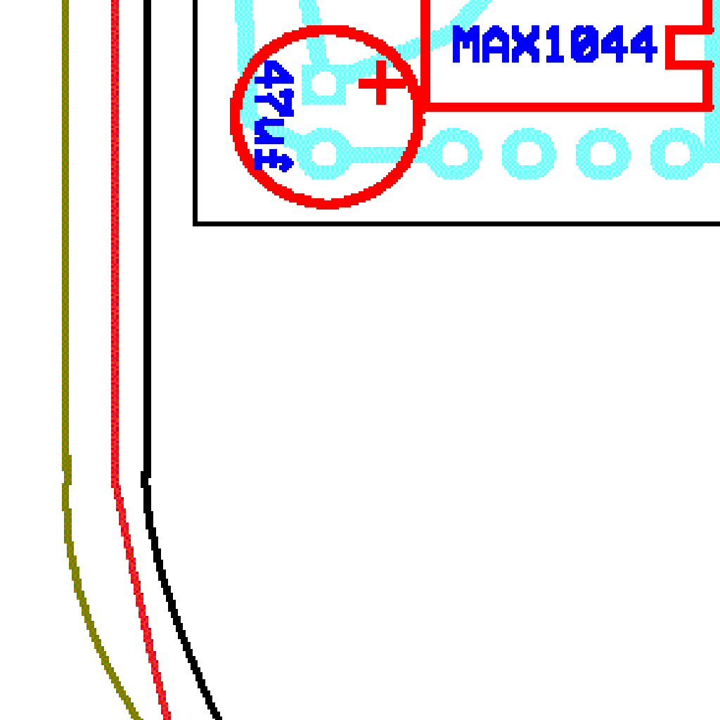
Fuzz Face™ Ready-For-Transfer Printed Circuit Board Layout - For use only if you are a complete DIY person who wants to etch and drill your own PCB. Otherwise, we recommend you ignore this PCB mask and buy the Ready-to-Solder Printed Circuit Board or Complete Kit from the links below.
Schematic
Schematic
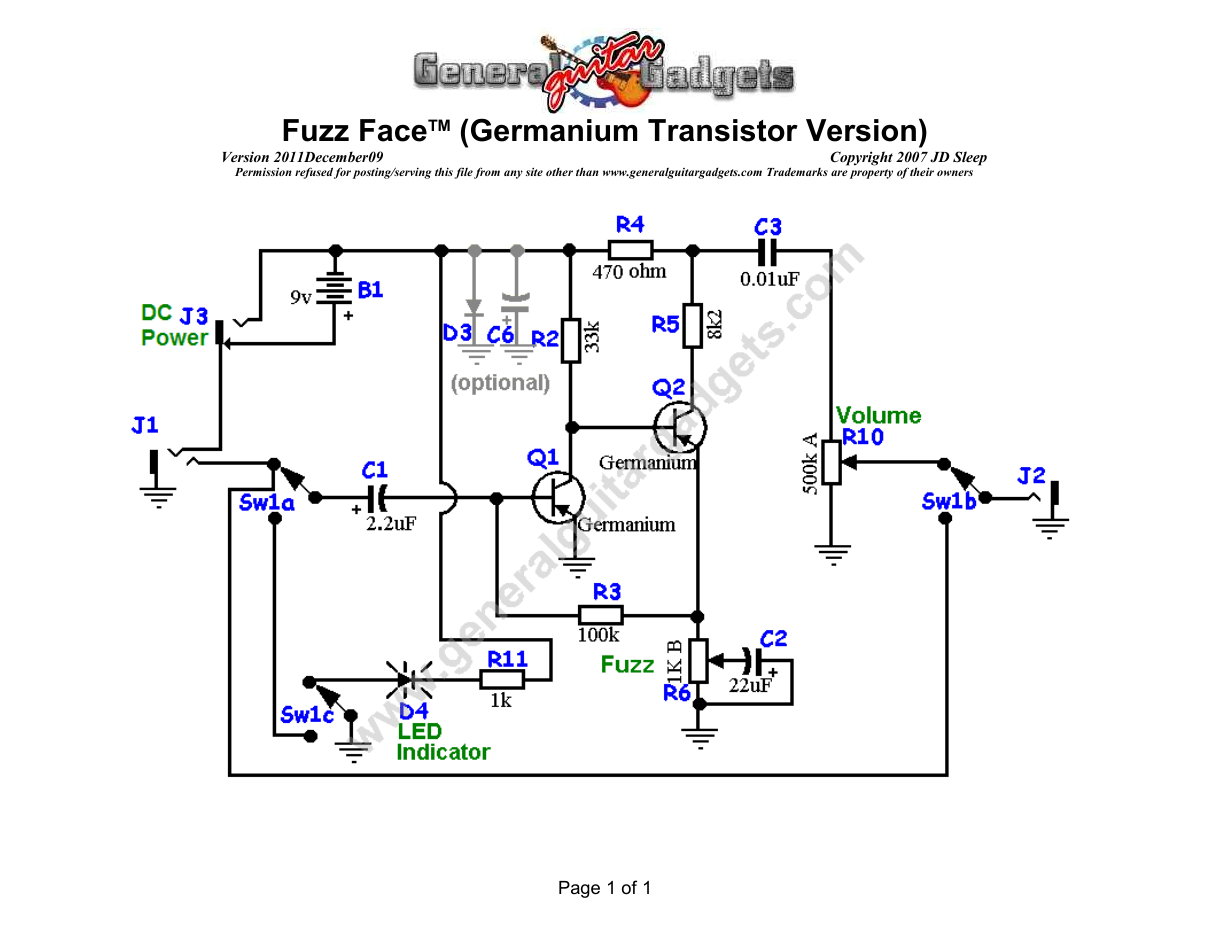
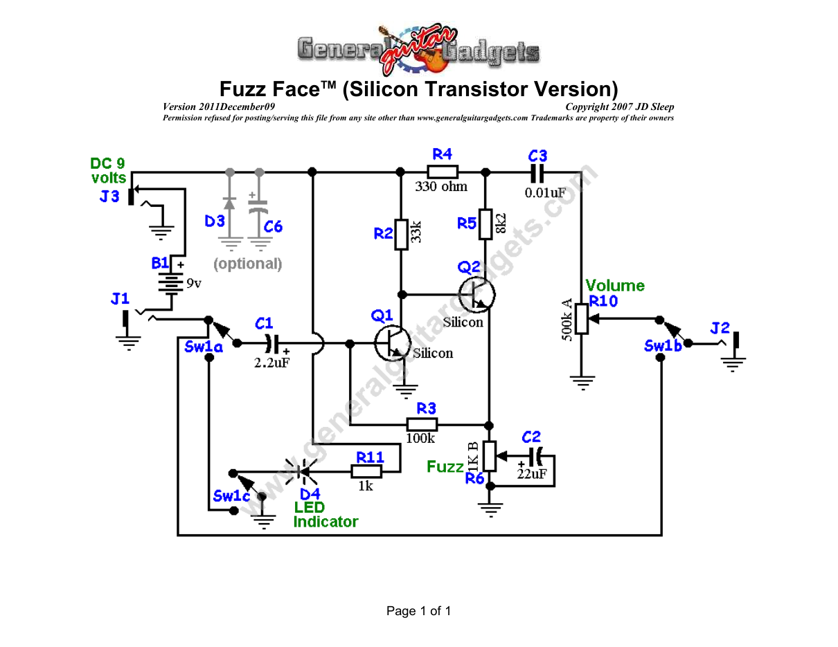
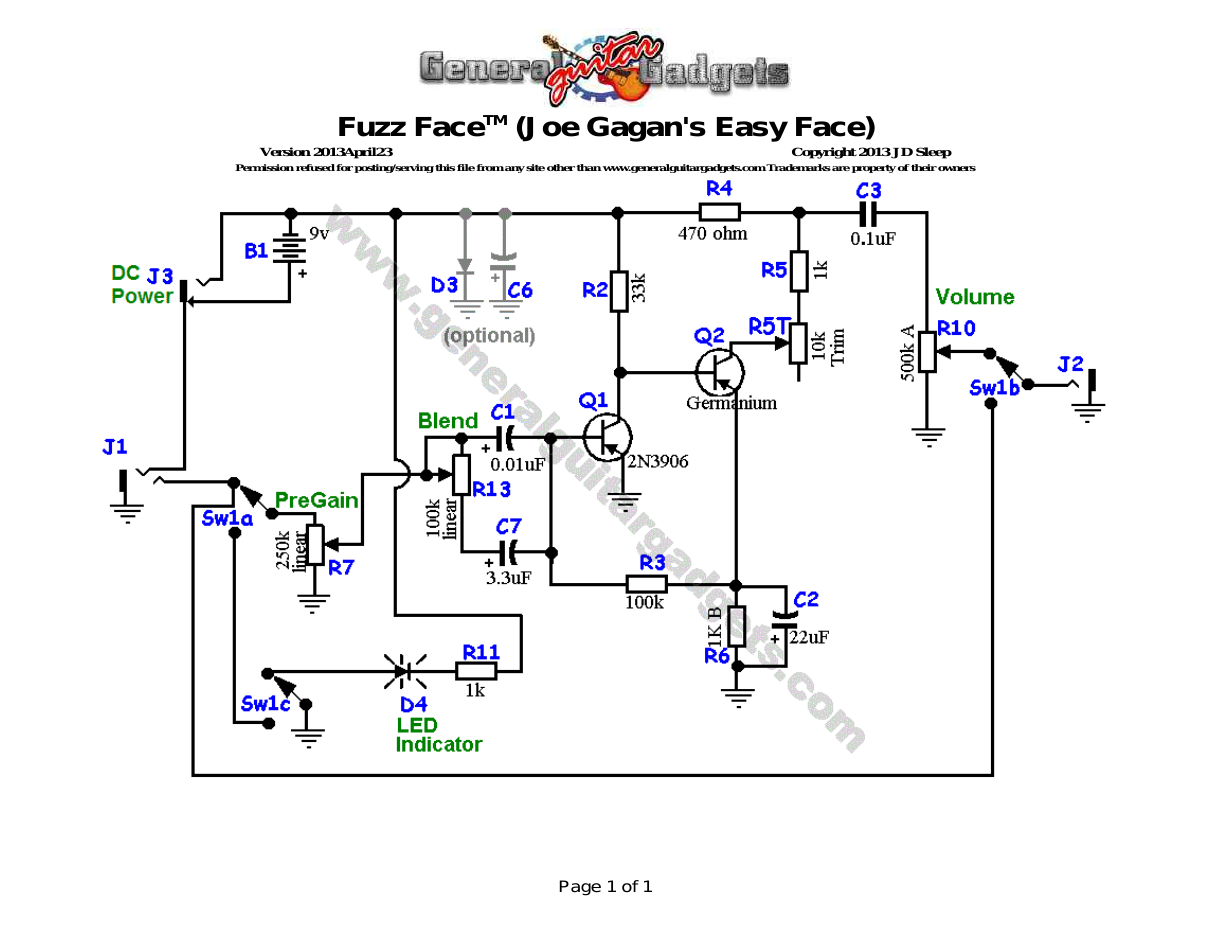
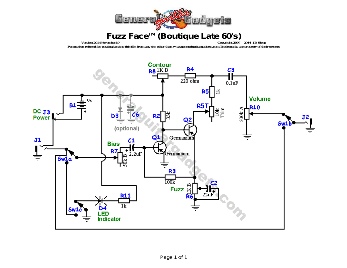
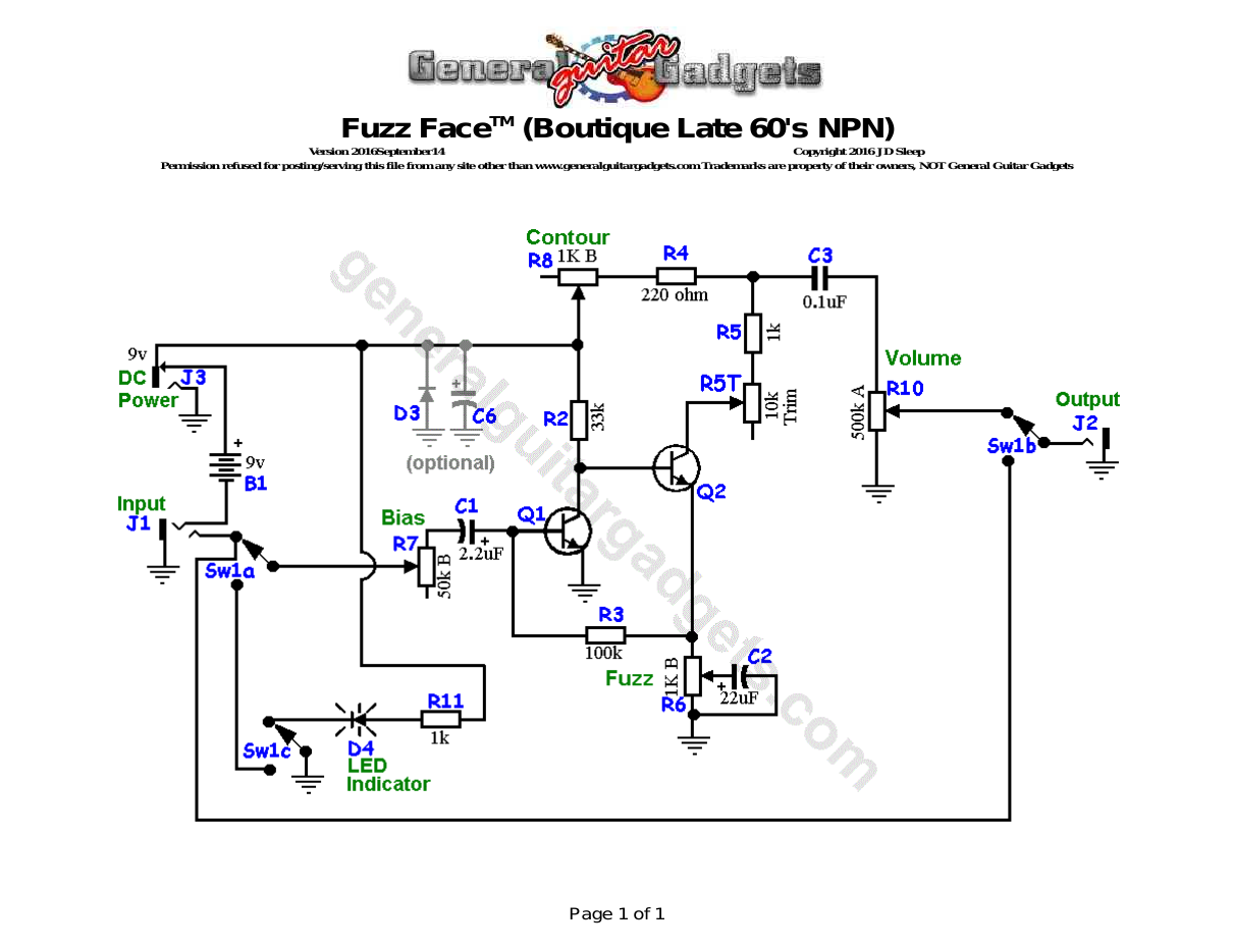
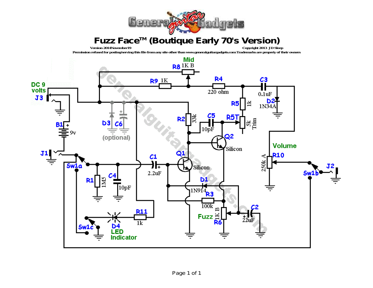
Parts layout
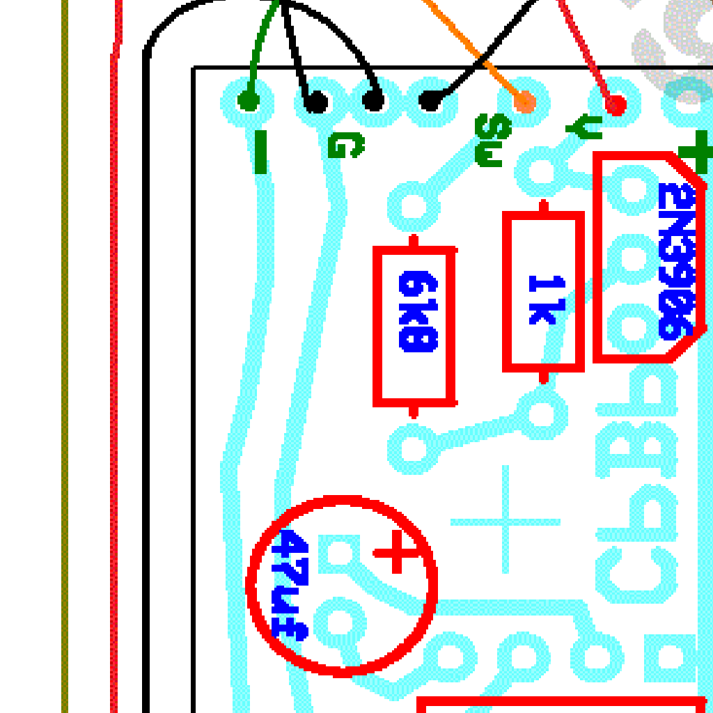
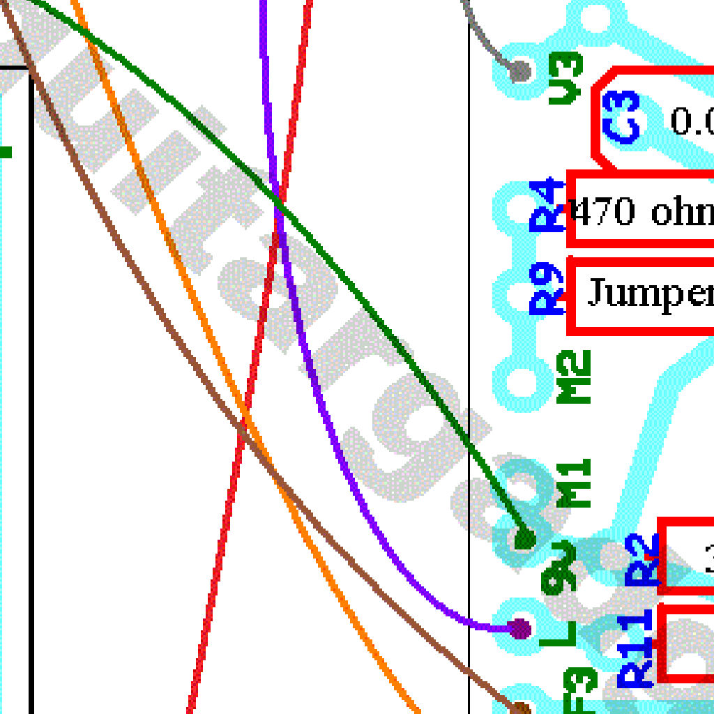
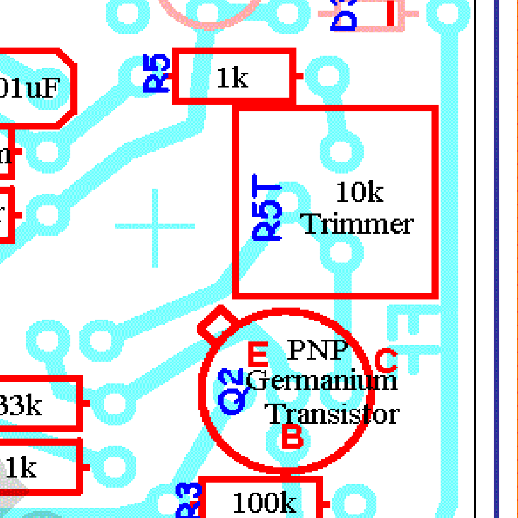
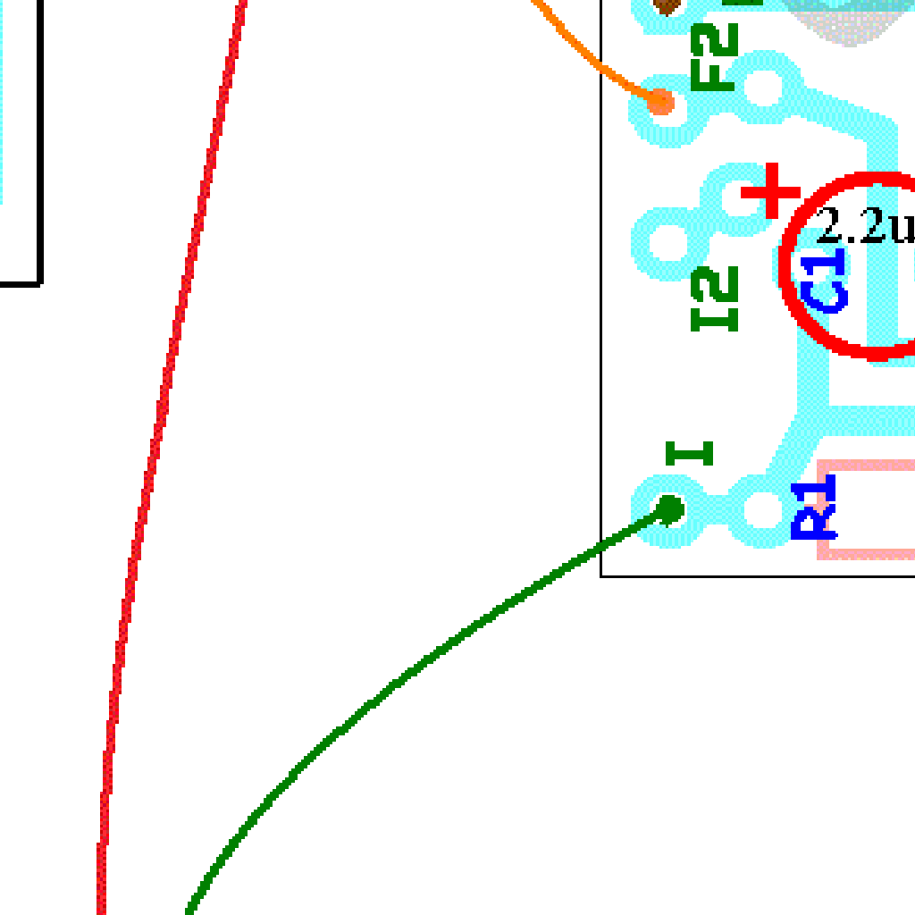
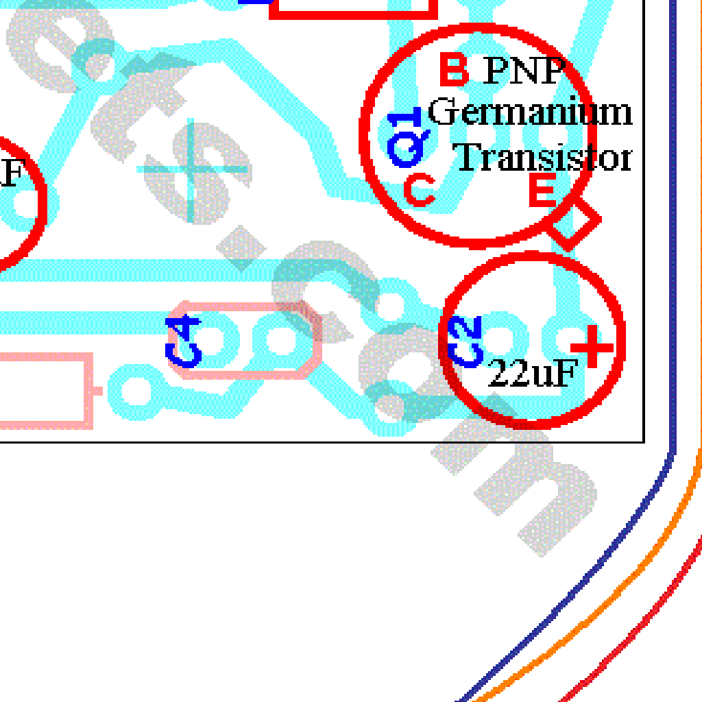
Parts Layout / Wiring Diagram
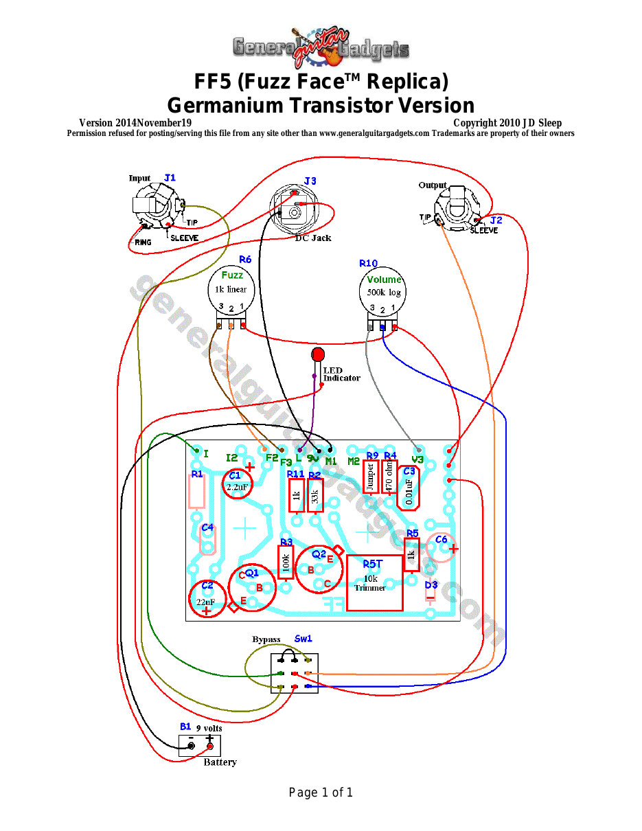
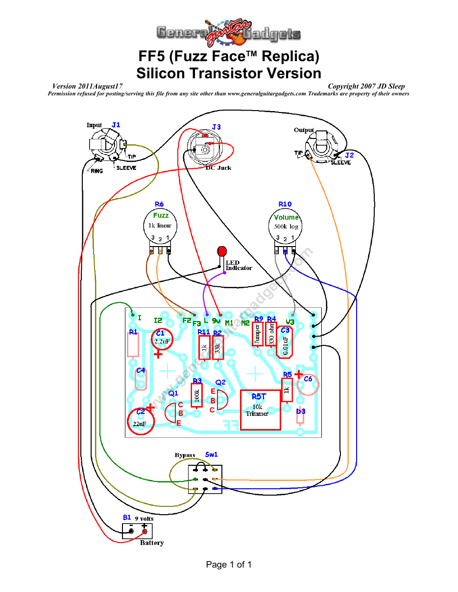
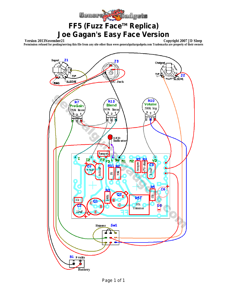
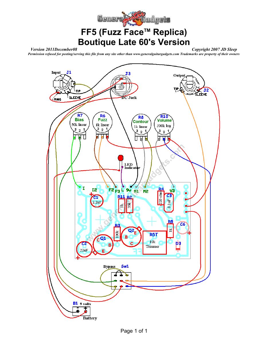
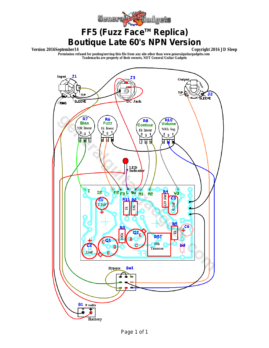
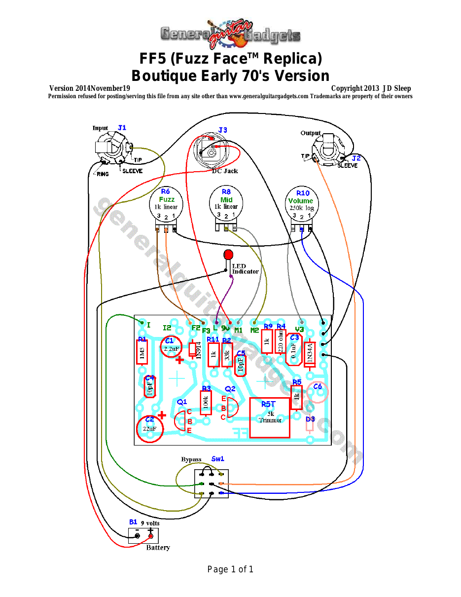
What you will need
Bill of Materials
Version 2009May26 · Copyright 2007 JD Sleep · Permission refused for posting/serving this file from any site other than www.generalguitargadgets.com · Trademarks are property of their owners
Resistors
| Resistor ID | Value | 3-band Marking | 4-band Marking |
|---|---|---|---|
| R1 (optional) | 1M5 (1.5M) | brown-green-green | brown-green-black-yellow |
| R2 | 33k | orange-orange-orange | orange-orange-black-red |
| R3 | 100k | brown-black-yellow | brown-black-black-orange |
| R4 | 470 ohm | yellow-violet-brown | yellow-violet-black-black |
| R5 (if R5T is | 8k2 (8.2k) | ||
| Jumpered) | gray-red-red | gray-red-black-brown | |
| R5 (if using R5T) | 1k | brown-black-red | brown-black-black-brown |
| R5T (optional) | 10k Trimmer Potentiometer | ||
| R6 | 1k Linear Potentiometer | ||
| R7 | None | ||
| R8 | None | ||
| R9 | None | ||
| R10 | 500k Audio Potentiometer | ||
| R11 | 1k | brown-black-red | brown-black-black-brown |
| R12 | None |
Capacitors
| Capacitor ID | Value | Type | Possible Marking |
|---|---|---|---|
| C1 | 2.2µF | Aluminum Electrolytic | 2.2µF |
| C2 | 22µF | Aluminum Electrolytic | 22µF |
| C3 | 0.01µF | Film | 103 |
| C4 (optional) | 100pF | Ceramic | 101 |
| C5 | none | ||
| C6 (optional) | 100µF | Aluminum Electrolytic | 100µF |
| C7 | None |
Potentiometers
| Part ID | Value | Type |
|---|---|---|
| R6 - Fuzz Control | 1k | Linear Taper |
| R10 - Volume Control | 500k | Log (or Audio) Taper |
Other
| Part ID | Part Name |
|---|---|
| D1 | none |
| D2 | none |
| D3 | 1N914 (optional) |
| D4 | LED |
| Q1 | Germanium Transistor (See Instructions) |
| Q2 | Germanium Transistor (See Instructions) |
| J1 | Stereo quarter-inch jack |
| J2 | Mono quarter-inch jack |
| J3 | DC Jack |
| B1 | 9 volt battery (not included in the Kit) |
| Sw1 | Heavy Duty 3PDT foot switch 9v battery snap, Printed Circuit Board, 24 gauge stranded wire, Enclosure, Knobs |
How to build it
Instructions
Fuzz Face™ Instructions
Version 2014November19 · Copyright 2007 – 2014 JD Sleep · Permission refused for posting/serving this file from any site other than www.generalguitargadgets.com · Trademarks are property of their owners
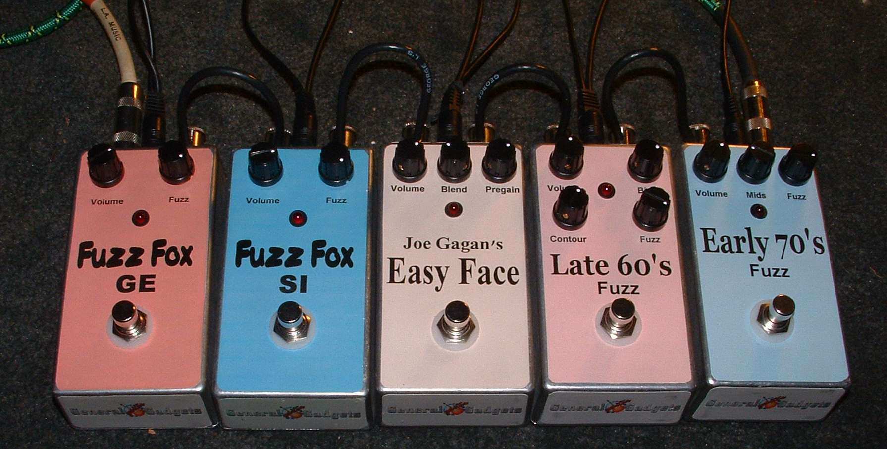
We call this project FF5, since there are at least 5 versions of fuzztones that you can build on the PCB. We titled this photo "Shoot Out at the Fuzz Face™ Corral". This instructions document covers all the versions of the Fuzz Face™ Projects on the site, these are: Dallas Arbiter™ Fuzz Face™
PNP
Germanium Transistors
Dallas Arbiter™ Fuzz Face™
NPN Silicon Transistors
Negative Ground
Boutique Late 60's
PNP
Positive Ground
Boutique Early 70's
NPN Silicon Transistors
Negative Ground
Easy Face
PNP
Positive Ground
Germanium Transistors
1 - Si & 1 - Ge Transistor
Positive Ground
Any 5 of these versions can be built on the same PCB! It is important to
thoroughly read all instructions before you start building. ●
●
Throughout this document we will use the table of elements abbreviations for Silicon and Germanium transistors. These are: Si for silicon and Ge for germanium. If you are new to DIY, you may be overwhelmed by the options and decisions you will have to make to build this project. If this is the case, buy the kit and
●
●
●
●
●
●
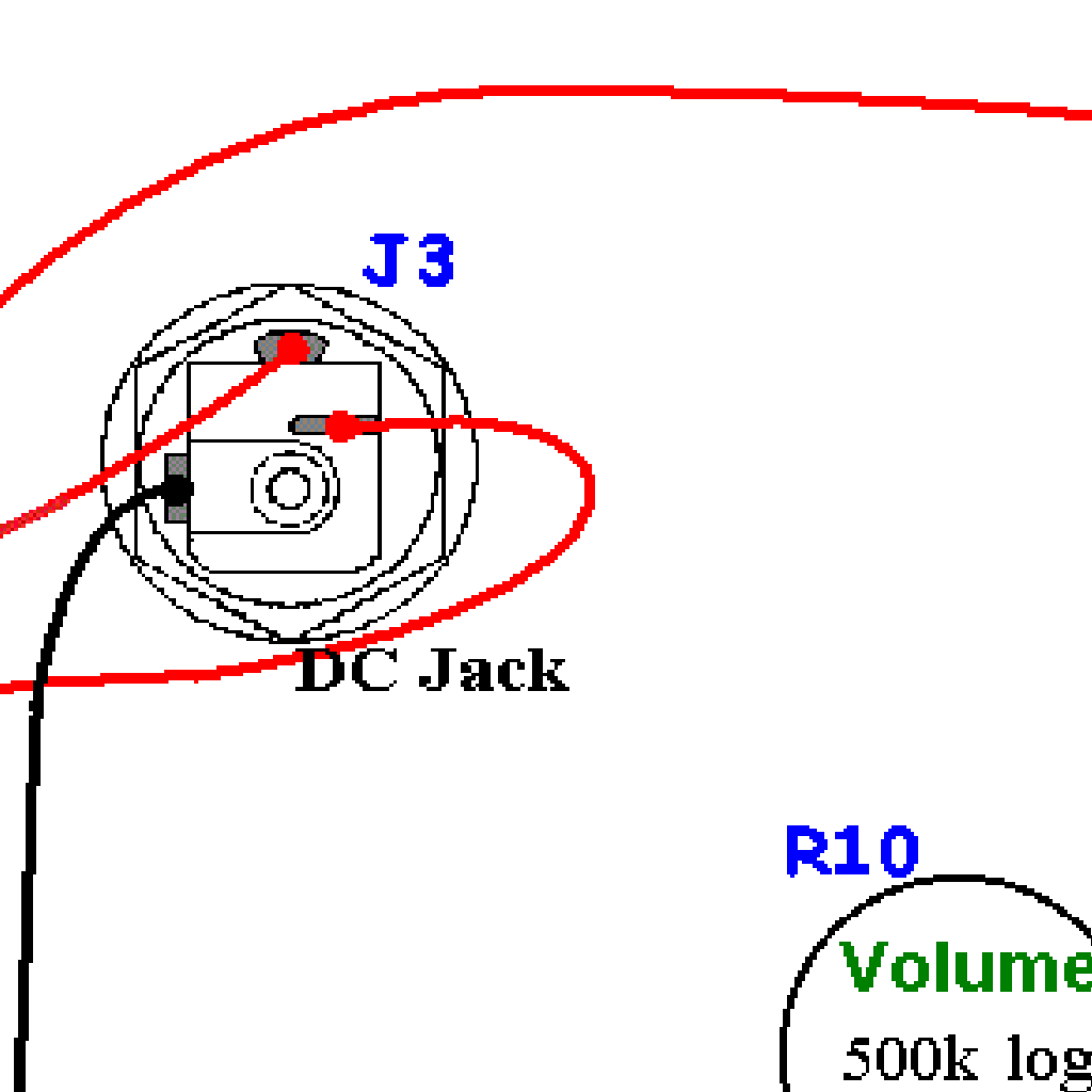
build the NPN Si Transistor version and enjoy. You may be surprised at how good Si transistors sound. You may have heard about the smooth tone you get from Ge transistors in the Fuzz Face™. With the transistors in the kit and tuned with the trimmer, you can get some great fuzz face sounds. Eric Johnson is known to use a Si transistor version Fuzz Face™ with excellent tone results. Be sure to see the document in the "Tech Pages" section on our site (How do I Build it/ Technical Help / Powering Your Effects / Basic Information...). This covers the general topic of wiring DC Power inside stompboxes. This is especially important if you are building one of the positive ground versions. Don't confuse the way the DC jack is wired with the way positive or negative ground circuits are wired. Even if the circuit is positive ground, we still wire the DC jack with a negative center pin. This can make life a little simpler since you can use any of the typical stompbox power supplies and you don't have to have a special power supply for your Fuzz Face™. If this doesn't make sense to you, study the link on the previous bullet. If you daisy chain power to your pedals, check out the Charge Pump “wrapper” on the Fuzz Face™ project page. It is possible to daisy chain your positive ground Fuzz Face™ with all your other (negative ground) pedals if you add this additional wrapper inside your pedal. We found that low gain Si PNP transistors usually sound very good in place of Ge transistors in all versions featured here. The kits include these Si transistors and we suggest that you try them out before you invest in Ge transistors. The Kits include sets of low-gain NPN and PNP Si transistors, if you wish to use Ge or other specialized transistors, you will also need to order those from a reputable dealer such as Small Bear or AMZ. Our kits include a 1k C (reverse log taper) for the Fuzz control instead of the 1k B that the originals have. It is a known fact that the reverse log taper gives a much better rotation for the fuzz control. We wouldn't have made this upgrade if we weren't absolutely sure this is a worthwhile improvement. You can use a 1k B and it will work fine, but we like the 1k C better. We have left the schematics and diagrams to show a 1k B since that is the original value. Using the same PCB board for both negative ground and positive ground version can present some deviations from the norm. We decided to default to negative ground wire colors for all versions. The polarization markings for polarized parts is no longer marked on our PCBs, so follow the parts placement diagrams, they will be different for negative and positive ground versions.
●
●
●
●
●
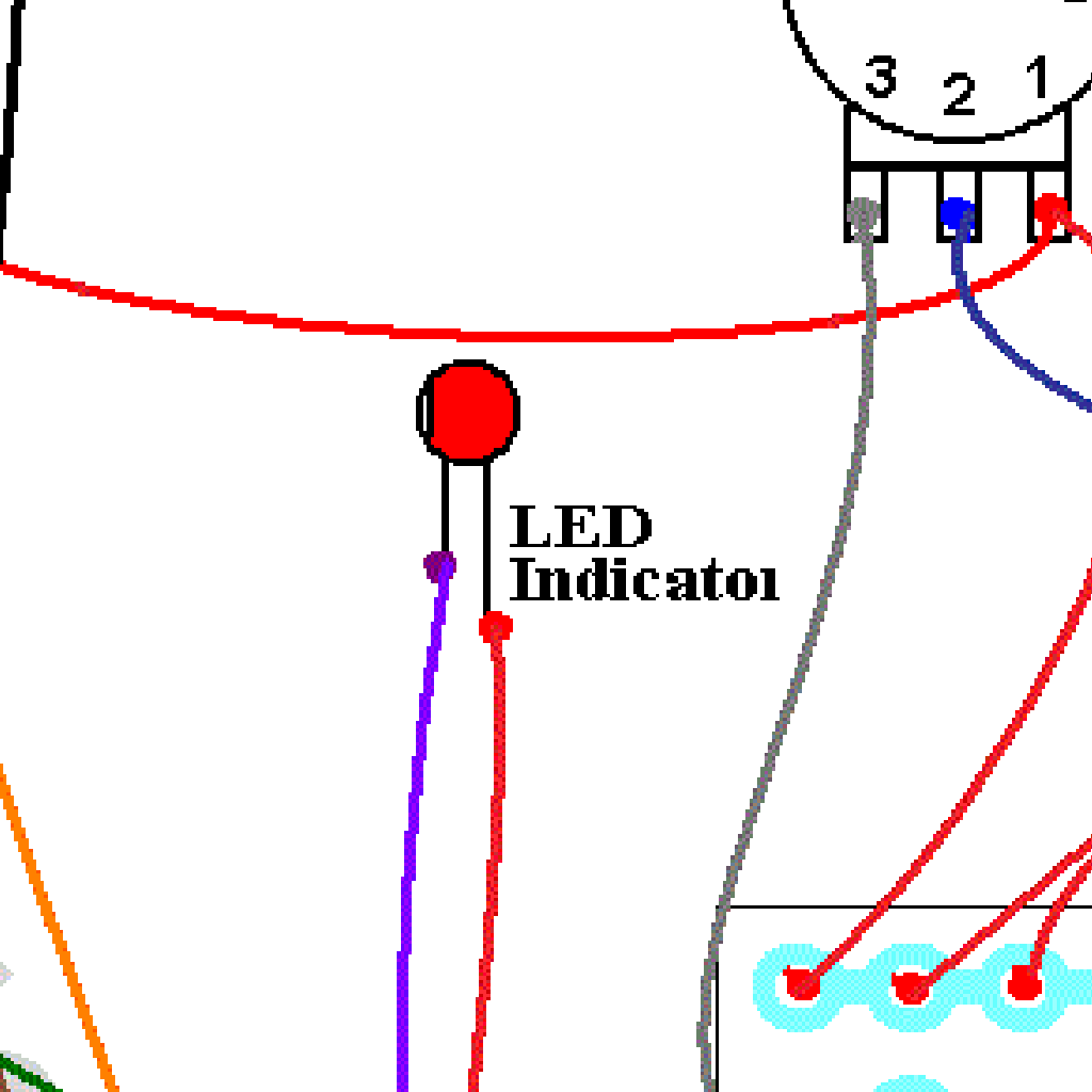
We always recommend that you use inexpensive Si transistors to build the Fuzz Face™ and get it working. Once you are sure it is all working correctly, replace the Si transistors with your Ge transistors. This will reduce the possibility of damaging your valuable Ge transistors. The kit includes high quality transistor sockets and a set of inexpensive (but good sounding) Si PNP transistors to use permanently or until after you get it tested for use with the Ge transistors. Note that the original Fuzz Face™ circuits did not have a trimmer in R5, what we have called R5T. We have included this trimmer in the parts placement diagrams because we believe it is a good feature to tune in a good tone. If you want to go without the trimmer, just run a jumper across R5T and adjust the value of R5 as the "Fuzz Face™, No Trimmer" diagram file on the project page shows. All versions may include the optional parts: R1, C4, C6 and D3. This is personal preference for you, the builder, whether to include them or not. R1 (1M5 resistor) may eliminate pop from the bypass switching. R1 PCB placement is not applicable for the Late Sixties and Easy Face versions since they have potentiometers on the front end. C4 (10pF or 100pF capacitor) may eliminate or reduce RF interference. C6 (100uF capacitor) is a power filter and D3 (diode) is for reverse voltage protection. Note that including D3 will reduce the voltage to the circuit. The amount of reduction is based on the type of diode used. A 1N914 will reduce voltage to the circuit by about one volt (this is not necessarily a bad thing for this circuit). C4 is not needed if you plan on using only battery power. Note that the LED leads are reversed for the PNP versions. The current limiting resistor (R11) can be placed on either lead of the LED, so the part and wiring remains the same on the PCB for all versions. Don't be afraid to "hybrid" any aspect of these versions. For example, you could try the "Easy Face" Blend Control on any of the other versions. The Pre-Gain control (as in the Easy Face) is a very useful addition to any version. Use your "tonal taste buds" and imagination to put together something that works best for you.
Follow the general building instructions and use the appropriate diagrams for the version you are building. Here are some steps to take to get started building from the kit: 1. Decide what version you are building. You can build the Dallas ArbiterTM Ge or
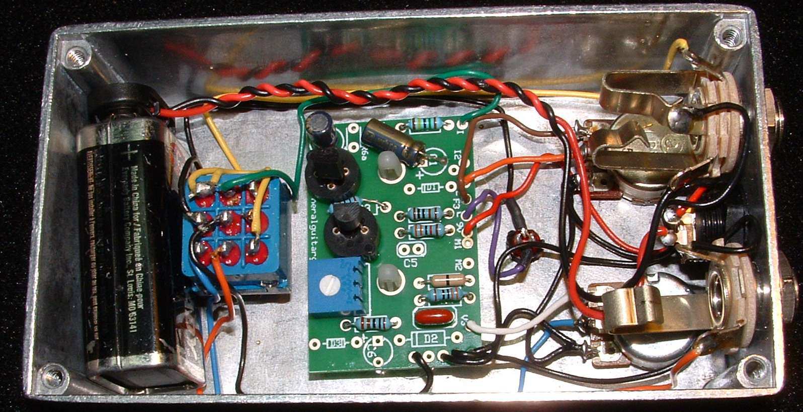
Si transistor version with the base kit (no options). The other versions require the purchase of a kit option. 2. Use the Bill of Materials and Parts Diagram for the version you are building to sort out the kit parts. You will have some extra parts that you will not use, as there are parts included for several options and versions. 3. NPN versions use the pair of 2N3904 or PN2369A transistors. PNP versions use the pair of 2N3906 transistors. 4. We don't include Ge transistors with any of the kits. After you get it built, you can easily downgrade to Ge transistors if you used the sockets. Side Note: The site previously featured the Fuzz Face™ project with PNP transistor versions and negative ground circuits. This idea can be found on many sites on the web. The first time we saw it was on AMZ. We found that for most builders, most of the time, this would cause oscillation or would cause funny things to happen to the sound when the guitar volume control was turned down (also related to oscillation). There are some stop-gap measures you can add to the circuit to minimize this, but we decided to release this version without the PNP/negative ground options. After having the PNP/negative ground projects on the site for several years, we feel that generally speaking it may be "compromising" this guitar effect to use this scheme or circuit. Our experience is that the odds of oscillation problems are greatly increased when building PNP/negative ground in the Fuzz Face™ circuit. PNP/positive ground is not a problem at all if you are using battery power. If you use a power supply, you will just need to have a separate supply for your PNP (positive ground) pedals, or build it with the Charge pump converter. Here's an inside view of the unit we built to give you a real view of our construction. This is the NPN version with the R1 optional resistor to eliminate switch pop.
Here is a chart of voltages taken at the transistor pins. Use these voltages as a guideline. You may not get the exact readings listed, but they should be close. This is also the NPN version.
Component
Location
9 volt power supply Q1
Q2
Voltage
9v
Collector
1.4v
Base
0.6v
Emitter
0.0v
Collector
4.5v (if you use a trimmer, you can set the voltage)
Base
1.4v
Emitter
0.8v
FF5 PNP Germanium with Charge Pump Instructions and Diagram
Version 2014November19 · Copyright 2014 JD Sleep · Permission refused for posting/serving this file from any site other than www.generalguitargadgets.com · Trademarks are property of their owners
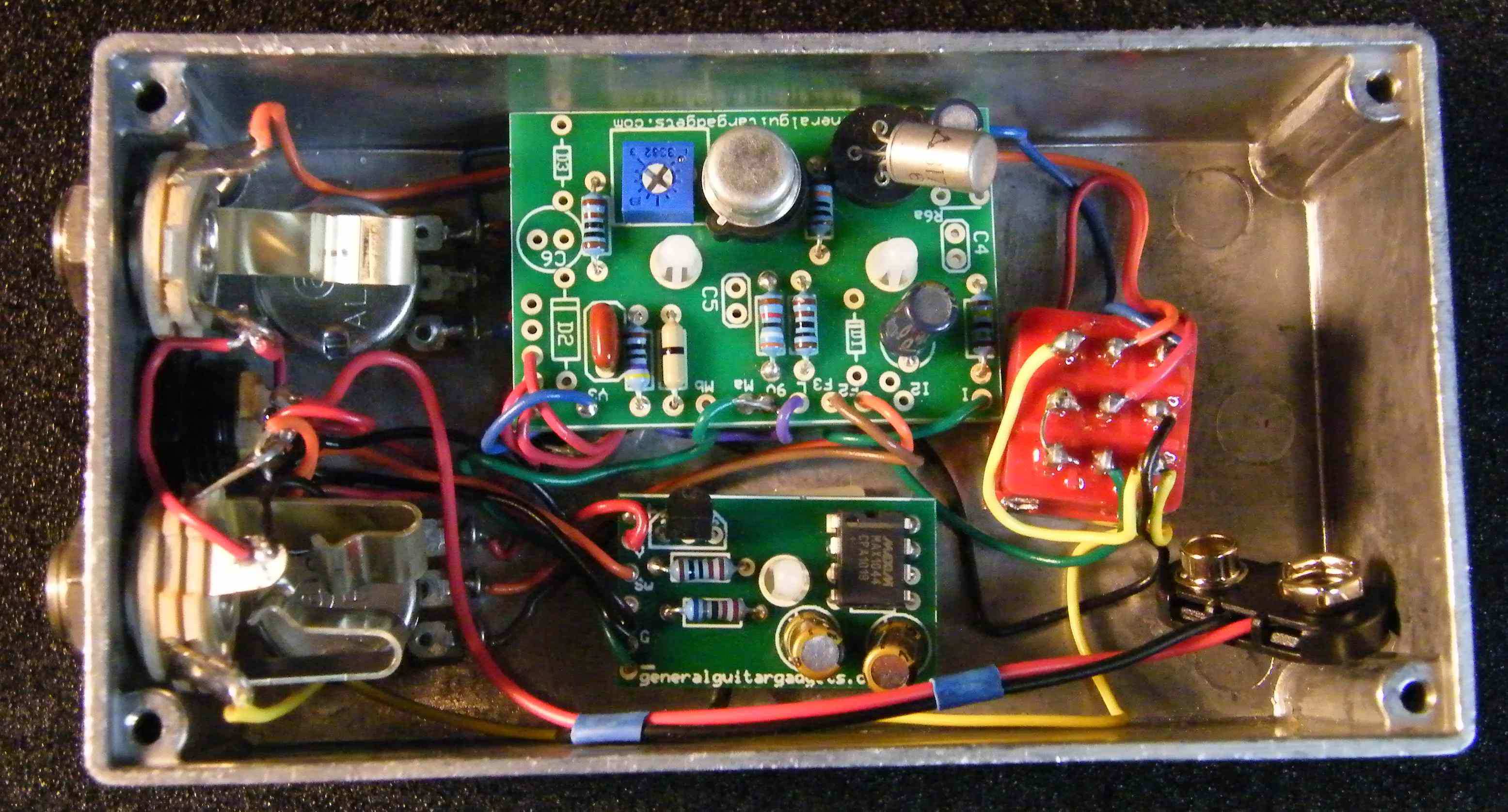
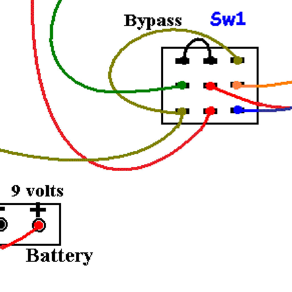
We ran across a forum post long ago where R.G. Keen suggested using a charge pump to convert the power input of a PNP circuit from positive ground to negative ground. This provides a solution for those of us who like to daisy chain a power supply to all of our stompboxes. If you've ever tried to daisy chain your modern pedals (Boss™, Ibanez™, etc) with a Fuzz Face™ (or an old 70's Big Muff Pi™ or any PNP transistor circuit pedal), you know you can't do it. Now you can! From the DC jack or battery, the charge pump circuit is a negative ground circuit. From the output of the charge pump circuit, we use the ground and -9v outputs to power the Fuzz Face™. The Fuzz Face™ circuit sees a positive ground (0v is more positive than -9v). So here is the solution for the FF5 PNP versions in diagram and photo. This is a great “wrapper circuit” to install and probably well worth the time in the long run. Here's a photo of a Dallas Arbiter™ type Fuzz Face™ replica with the charge pump.
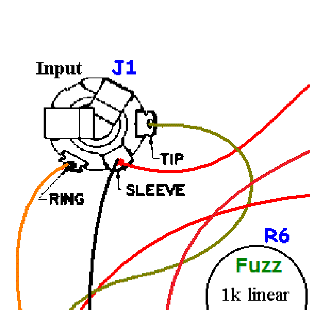
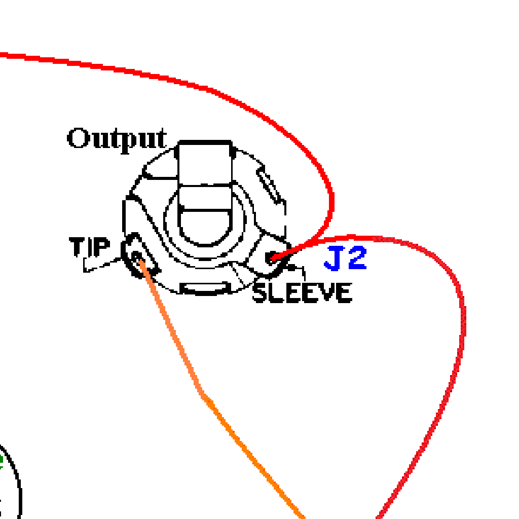
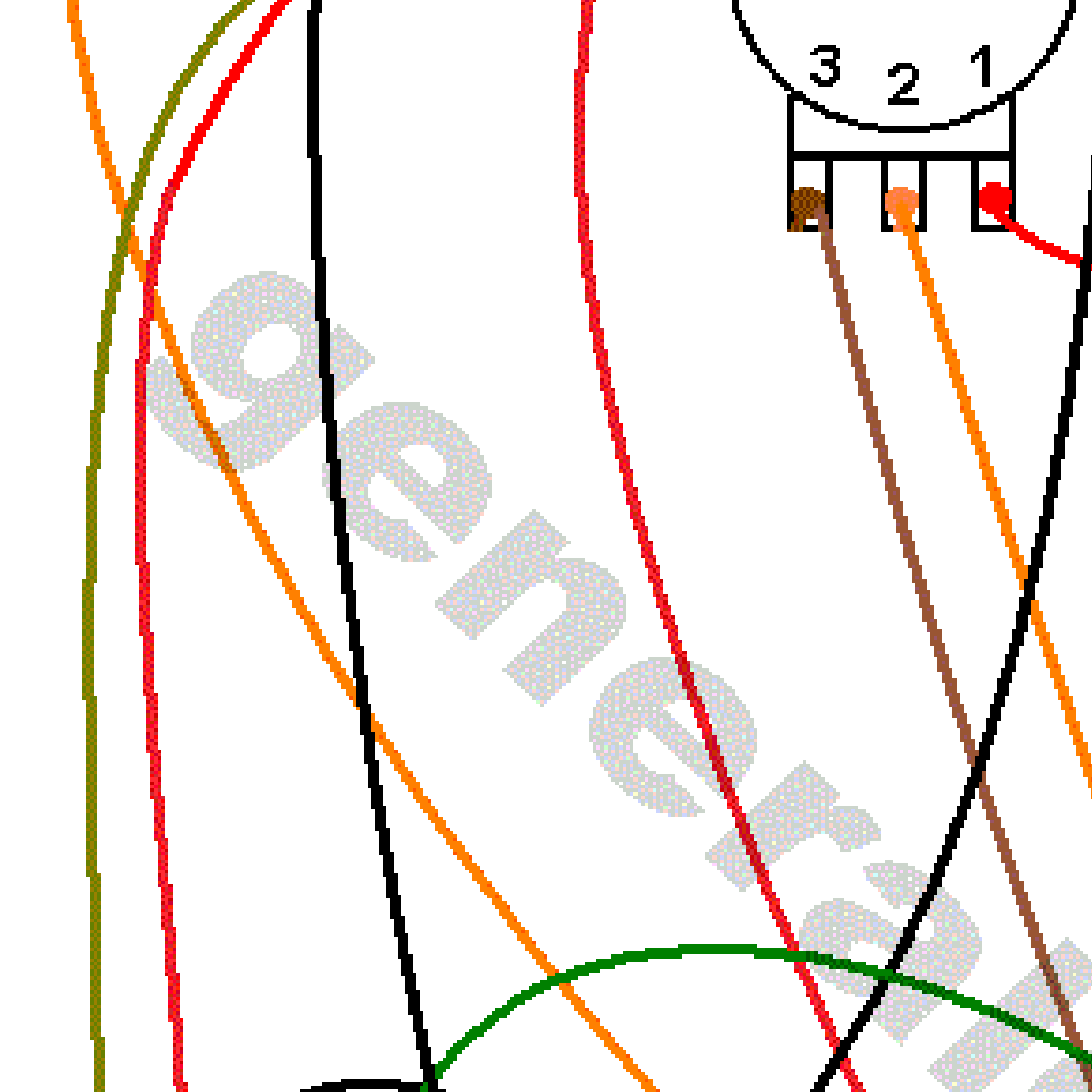
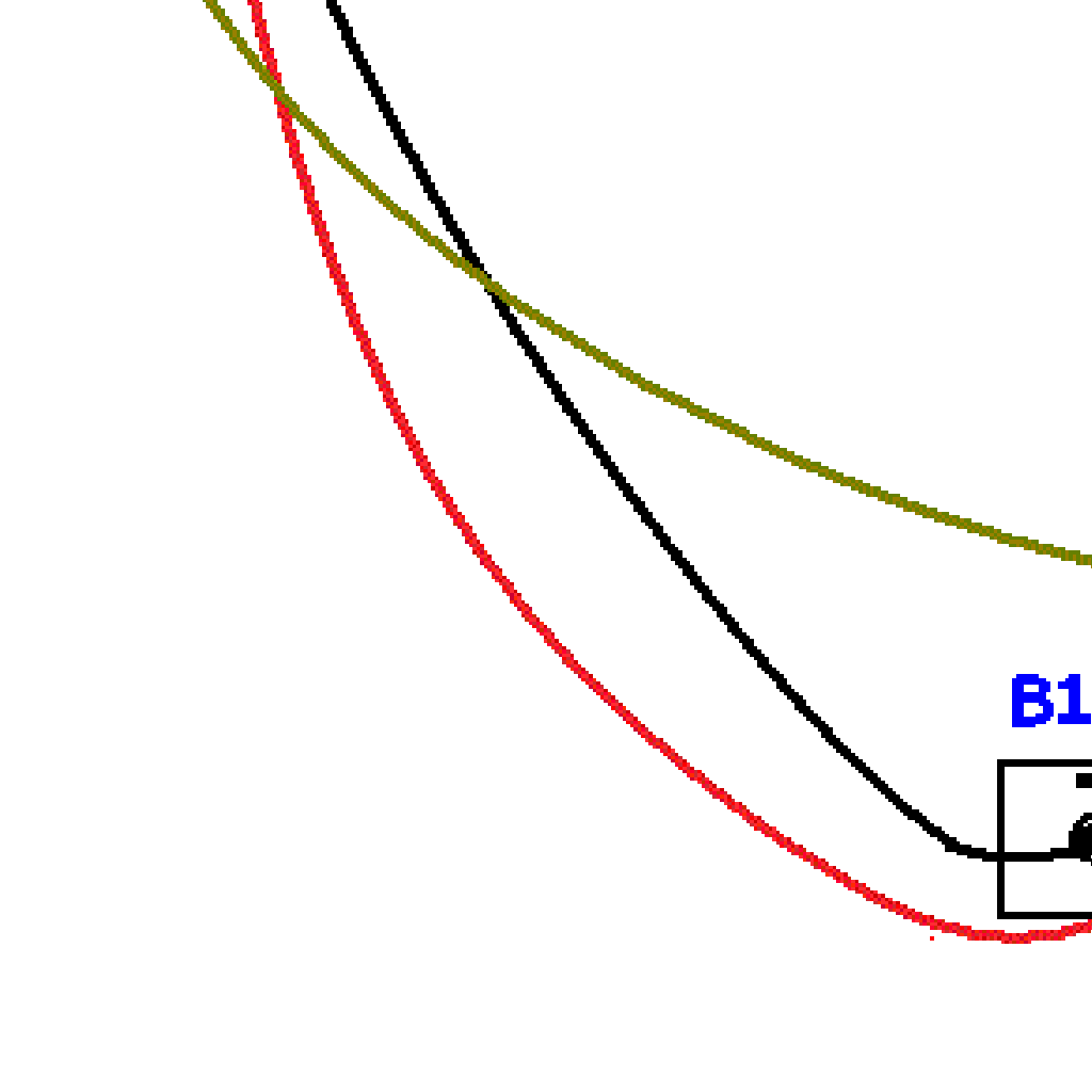
Here's the wiring diagram for the Dallas Arbiter™ Fuzz Face™ Replica with charge pump (next page).

Questions
Frequently asked questions
Germanium or silicon?
Silicon is cleaner-sounding, stable in any weather and the easiest first build. Germanium is the warmer, smoother 1966 sound but temperature-sensitive. The kit ships silicon; germanium transistors fit the same sockets.
Does the kit include germanium transistors?
No. They vary too much to supply blind; the sockets let you fit your own matched pair after proving the circuit with the silicon ones.
What is the bias trimmer for?
The original had no trimmer and relied on luck in transistor gain. The 10k trimmer lets you set Q2's collector to about 4.5 V, where a Fuzz Face™ sounds best, with any transistor.
Can I run a positive-ground version on my pedalboard supply?
Yes: the germanium charge-pump diagram lets a PNP build share a normal negative-ground supply with your other pedals.
More about this project
Notes, sounds and related links
- Fuzz Face™ with Germanium Transistor
- Fuzz Face™ with NPN Silicon Transistor
- Joe Gagan's Easy Face
- Boutique Late 60's Fuzz Face™ (PNP)
- Boutique Late 60's NPN Fuzz Face™
- Boutique Early 70's Fuzz Face™
For a simple project, we recommend the NPN Silicon Transistor Version. If you want to build a Germanium Transistor version, get your transistor set from Small Bear Electronics LLC and use the resistor values that he sends with the transistors. His resistor designations (R2, etc) are not the same as the designations on these projects. Here is the cross reference:
- SBE R3 - GGG R2
- SBE R4 - GGG R4
- SBE R5 - GGG R5 (may not be needed if you use R5T trimmer)
- SBE R6 - GGG R3
If you have a common power supply to power your pedals, the negative ground version will work with your other pedals on a common power supply. See the Charge Pump Wrapper below to get your positive ground pedal on a common power supply with all your other pedals.
Trimmer or No Trimmer
The Germanium Transistor version and The NPN Silicon Transistor version layouts both have a 10k trimmer (R5T) that is not shown in the schematic. We believe this is a worthy addition to the circuits, giving you more options for the ultimate sound you want. If you don't want to use the trimmer, here is the Fuzz Face™, No Trimmer Diagram mentioned in the Instructions file. This diagram is for the Germanium Transistor version, but the jumper is the same for the NPN Silicon Transistor version.
Common Files For All Versions
Fuzz Face™ Germanium Transistor (Dallas Arbiter™) Version
Fuzz Face™ Silicon Transistor (Dallas Arbiter™) Version
Easy Face (Joe Gagan's) Version
Boutique Late 60's Fuzz Face™ Version
Boutique Late 60's NPN Fuzz Face™ Version
This can use silicon or germanium NPN transistors with excellent results. Bill of Materials is the same as the "Late 60's Bill of Materials above.
Boutique Early 70's Fuzz Face™ Version
Fuzz Face™ PNP Germanium Transistor With Charge Pump Version
The addition of a charge pump on the input power, gives you the ability to daisy chain power to your PNP Positive ground pedal with all your other negative ground pedals! Eliminate any need for special considerations when powering your Fuzz Face™ with the other pedals on your pedal board.

Ready to build? We have the kit.
Buy a FF5 Complete Kit. Includes all the parts and materials you need to build one, all for about the price you would pay for a PCB and parts.

Would you like a Ready to Solder Circuit Board for this project? Note: If you buy the kit, the Ready-to-Solder Printed Circuit Board (RTS PCB) is included in the kit. You do not need to purchase this Ready to Solder Circuit Printed Board if you buy the kit.