
Project · Fuzz Tones
ColorSound™ ToneBender™ (Mark II Professional)
This is the classic, vintage ColorSound™ ToneBender™ Mark II Professional. There are the three variations of the Mark II Professional. Options are to build it with PNP or NPN germanium transistors or with NPN silicon transistors
This same stompbox may have been sold during the same time period under the name of SolaSound™ ToneBender™ and possibly Vox™™ ToneBender™. There seems to be possibly some small differences in some of the part values between the circuits inside the different brand names.
For a simple and great sounding ToneBender™, build the silicon transistor version. The kit includes everything you need if you use silicon transistors. If you want to build a germanium transistor version, you can get your transistor set from Small Bear Electronics LLC and use the resistor values that he sends with the transistors. His resistor designations (R2, etc) match the designations on these projects.
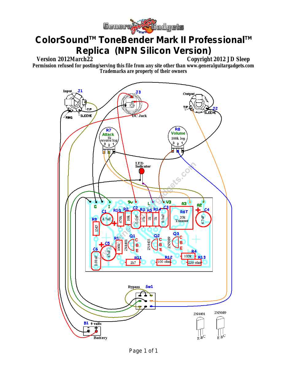
The documents in this first section are shared by all versions. All versions use the same PCB and the same wiring diagram. Parts layouts and schematics for each of the versions are listed as you go down the page.
Project files
Everything you need to build it
ToneBender™ Mark II Ready-For-Transfer Printed Circuit Board Layout - For use only if you are a complete DIY person who wants to etch and drill your own PCB. Otherwise, we recommend you ignore this PCB mask and buy the Ready-to-Solder Printed Circuit Board or Complete Kit from the links below.
Schematic
Schematic
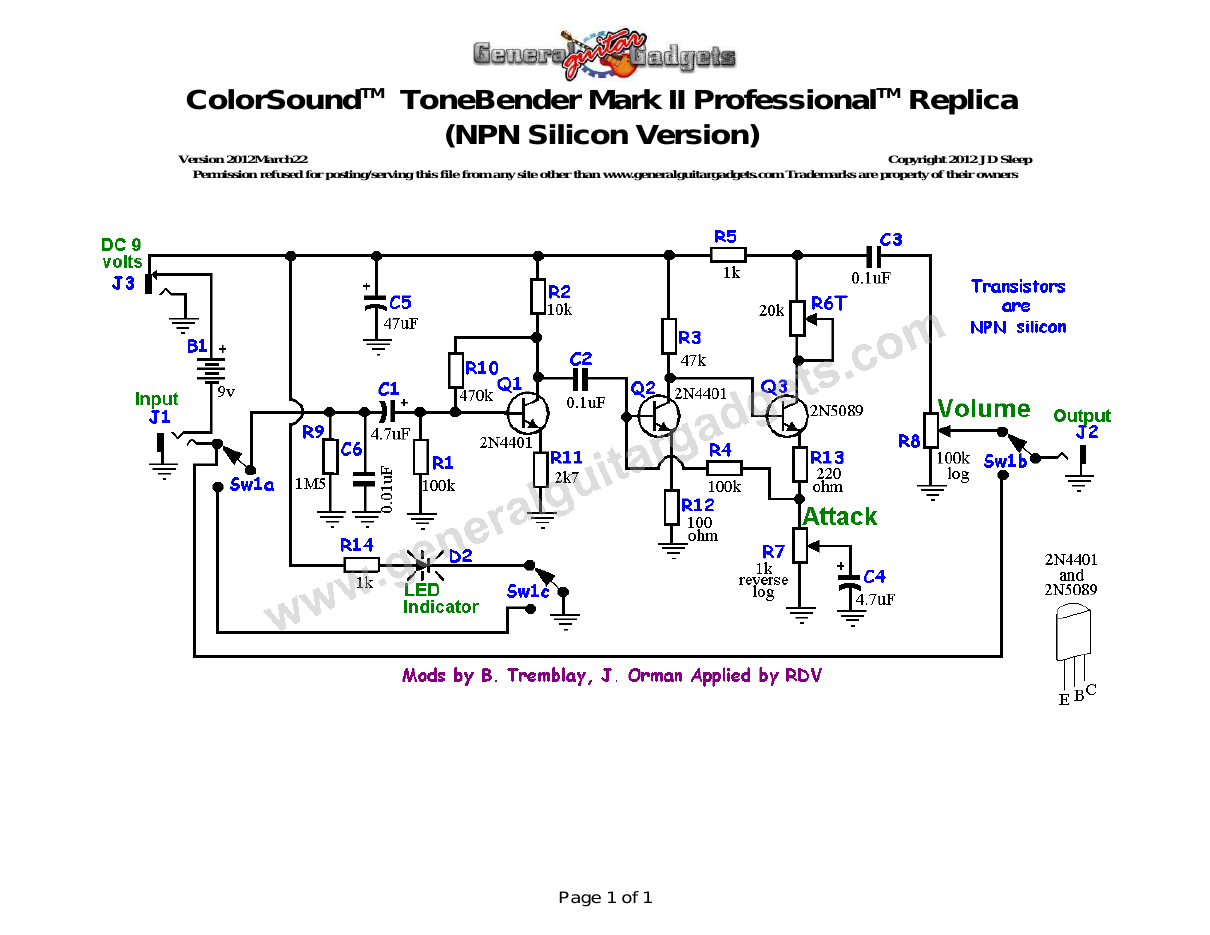
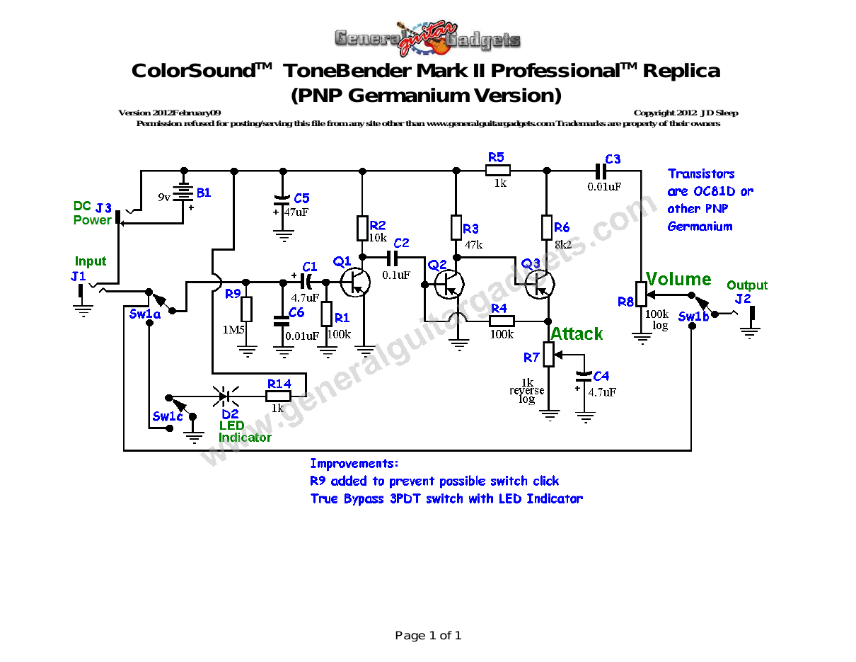
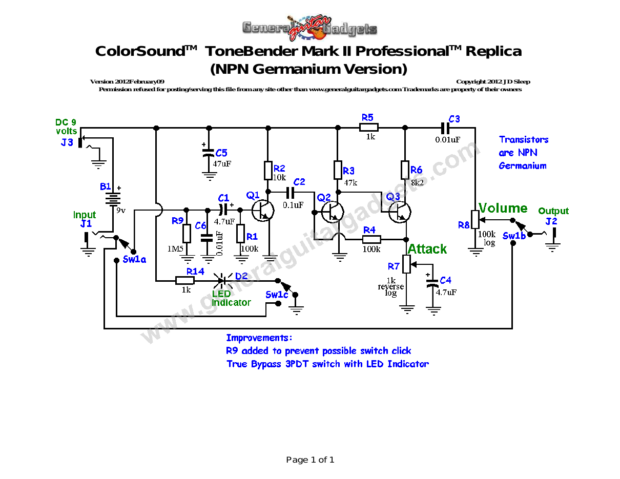
Parts layout
Parts Layout / Wiring Diagram
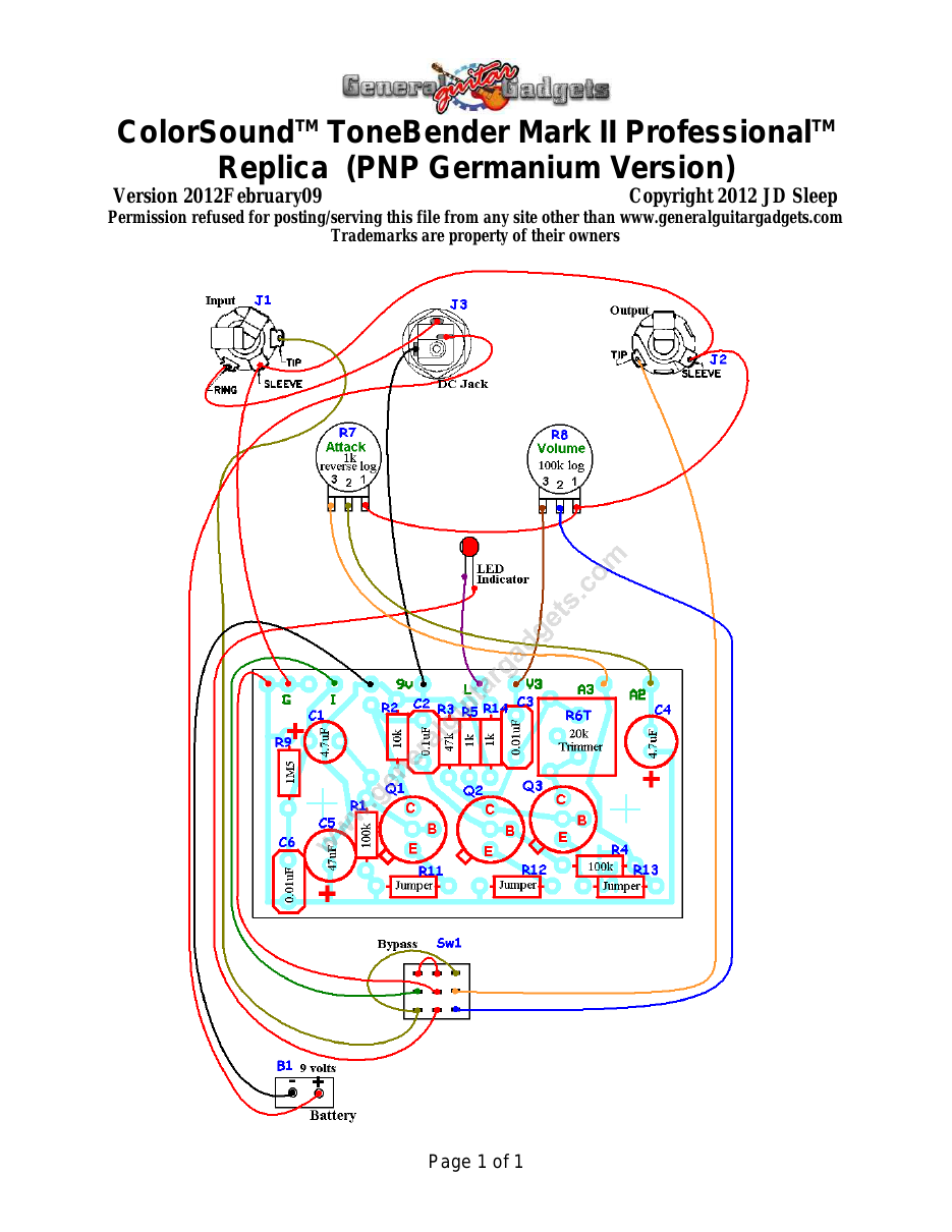
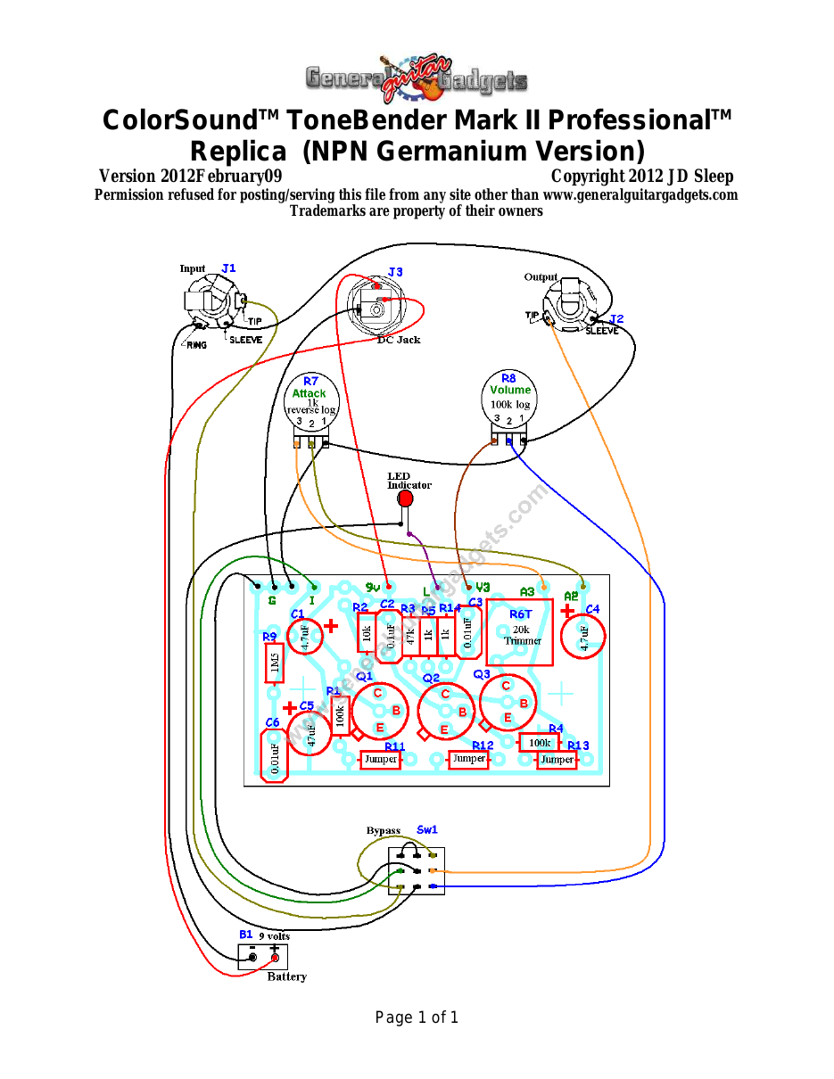
What you will need
Bill of Materials
Version 2012July26 · Copyright 2012 JD Sleep · Permission refused for posting/serving this file from any site other than www.generalguitargadgets.com · Trademarks are property of their owners
Resistors
| Resistor ID | Value | 3-band Marking | 4-band Marking |
|---|---|---|---|
| R1 | 100k | brown-black-yellow | brown-black-black-orange |
| R2 | 10k | brown-black-orange | brown-black-black-red |
| R3 | 47k | yellow-violet-orange | yellow-violet-black-red |
| R4 | 100k | brown-black-yellow | brown-black-black-orange |
| R5 | 1k | brown-black-red | brown-black-black-brown |
| R6 | 5k6 (5.6k) | green-blue-red | green-blue-black-brown |
| R6T (optional | 20k | ||
| replacement for | Trimmer potentiometer | ||
| R6) | |||
| R7 (Attack Control Potentiometer) | 1k Linear | ||
| R8 (Volume Control Potentiometer) | 100k Log | ||
| R9 | 1M5 (1.5M) | brown-green-green | brown-green-black-yellow |
| R10 | 470k | yellow-violet-yellow | yellow-violet-black-orange |
| R11 | 2k7 (2.7k) | red-violet-red | red-violet-black-brown |
| R12 | 100 ohm | brown-black-brown | brown-black-black-black |
| R13 | 220 ohm | red-red-brown | red-red-black-black |
| R14 | 1k | brown-black-red | brown-black-black-brown |
Capacitors
| Capacitor ID | Value | Type | Possible Marking |
|---|---|---|---|
| C1 | 4.7µF | Aluminum Electrolytic | 4.7µF |
| C2 | 0.1µF | Film | 104 |
| C2 | 0.1µF | Film | 104 |
| C4 | 4.7µF | Aluminum Electrolytic | 4.7µF |
| C5 | 47µF | Aluminum Electrolytic | 47µF |
| C6 | 0.01µF | Film | 103 |
Potentiometers
| Part ID | Value | Type |
|---|---|---|
| R7 - Attack Control | 1k | Reverse Log Taper |
| R8 - Volume Control | 100k | Log (or Audio) Taper |
Other
| Part ID | Part Name |
|---|---|
| D2 | LED |
| Q1 | 2N4401 or other NPN Silicon bipolar junction transistor |
| Q2 | 2N4401 or other NPN Silicon bipolar junction transistor |
| Q3 | 2N5089 or other NPN Silicon bipolar junction transistor |
| J1 | Stereo quarter-inch jack |
| J2 | Mono quarter-inch jack |
| J3 | DC Jack |
| B1 | 9 volt battery (not included in the Kit) |
| Sw1 | Heavy Duty 3PDT foot switch 9v battery snap, Printed Circuit Board, 24 gauge stranded wire, Enclosure, Knobs |
How to build it
Instructions
ToneBender™ Mark II Instructions (voltage reading reference and photos)
Version 2013August18 · Copyright 2013 JD Sleep · Permission refused for posting/serving this file from any site other than www.generalguitargadgets.com · Trademarks are property of their owners
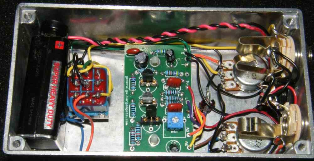
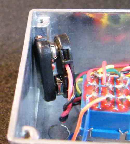
This is a replica of the ColorSound™ ToneBender™ Mark II Professional referred to as TB2 in these documents. The kit includes transistors to build a complete kit of the NPN Silicon transistor version. The kit also includes transistor sockets for PNP or NPN Germanium transistors that you provide. Follow the General Instructions and the layout diagram for the version you are building. You should set the trimmer to the sound you like. 4.5v is sometimes recommended, but a lower voltage sounds better to us. If you build the PNP version: there is a “down side” to the wiring we use. If you don't have a battery in the battery snap, it's possible that the battery snap can cause the power to short out if it touches the enclosure. We recommend that you cover the battery snap so that it can't short out. You can use tape to cover it or you can use a old used snap that you might have laying around as shown in the picture. Again, this is only for the PNP versions.
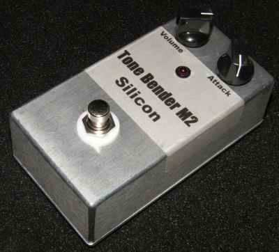
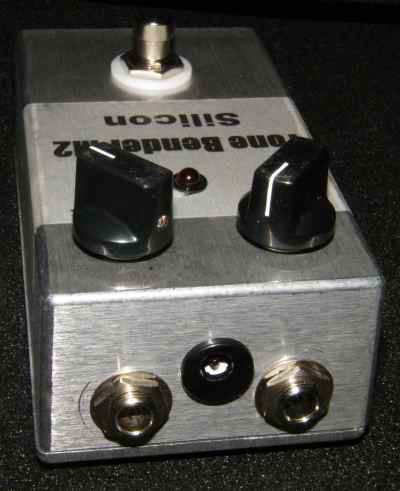
Here's an inside view of the unit we built to show some construction details.
Have fun, comments and questions are welcome and can be sent to [email protected] Here is a chart of voltages taken at the transistor pins. This information can be used
to help you find and fix problems if your TB2 doesn't work when you test it.
Silicon version
Component
Location
Voltage
9 volt supply Q1
Q2
Q3
9.4 (One Spot) Collector
7.06v
Base
1.2v
Emitter
0.6v
Collector
1.7v
Base
0.7v
Emitter
0.06v
Collector
4.5v (or your trimmer setting)
Base
1.7v
Emitter
1.1v
Germanium Version
Component
Location
9 volt supply Q1
Q2
Q3
Voltage
9.4 (One Spot)
Collector
-9.4v
Base
-0.03v
Emitter
0v
Collector
0.37
Base
0.09v
Emitter
0v
Collector
4.5v (or your trimmer setting)
Base
.67v
Component
Location
Voltage
Emitter
0.1v
ToneBender™ (Mark II Professional) PNP Germanium with Charge Pump Instructions and Diagram
Version 2015February03 · Copyright 2015JD Sleep · Permission refused for posting/serving this file from any site other than www.generalguitargadgets.com · Trademarks are property of their owners
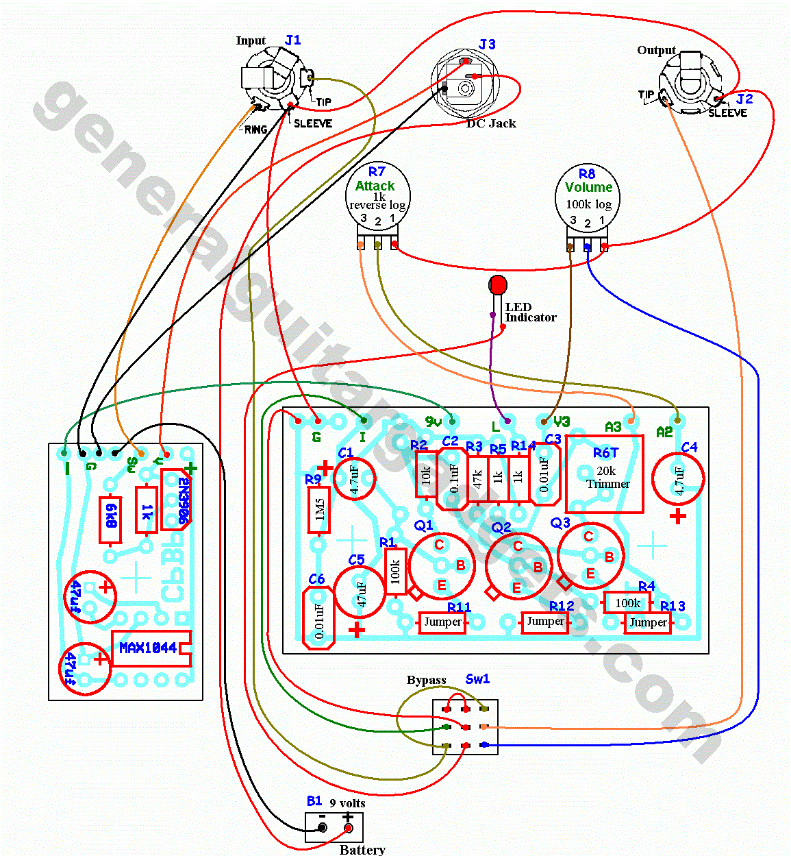
We ran across a forum post long ago where R.G. Keen suggested using a charge pump to convert the power input of a PNP circuit from positive ground to negative ground. This provides a solution for those of us who like to daisy chain a power supply to all of our stompboxes. If you've ever tried to daisy chain your modern pedals (Boss™, Ibanez™, etc) with a Fuzz Face™ (or a 70's Big Muff Pi™ or any PNP transistor circuit pedal), you know you can't do it. Now you can! From the DC jack or battery, the charge pump circuit is a negative ground circuit. From the output of the charge pump circuit, we use the ground and -9v outputs to power the ToneBender™. The ToneBender™ circuit sees a positive ground (0v is more positive than -9v). So here is the solution for the TB2 PNP versions in diagram and photo. This is a great “wrapper circuit” to install and probably well worth the time in the long run.
(Wiring diagram is on the following page)
Here's the wiring diagram for the ColorSound™ ToneBender™ Mark2 Professional Replica with charge pump (next page).
More about this project
Notes, sounds and related links
NPN Silicon Transistor Version
PNP Germanium Transistor Version
NPN Germanium Transistor Version
ToneBender™ (Mark II Professional) PNP Germanium Transistor With Charge Pump Version
The addition of a charge pump on the input power, gives you the ability to daisy chain power to your PNP Positive ground pedal with all your other negative ground pedals! Eliminate any need for special considerations when powering your Tone Bender™ with the other pedals on your pedal board.


YouTube Video comparing Silicon and Germanium transistor versions!
Ready to build? We have the kit.
Buy a TB2 Complete Kit. Includes all the parts and materials you need to build one, all for about the price you would pay for a PCB and parts.

Would you like a Ready to Solder Circuit Board for this project? Note: If you buy the kit, the Ready-to-Solder Printed Circuit Board (RTS PCB) is included in the kit. You do not need to purchase this Ready to Solder Circuit Printed Board if you buy the kit.