
Project · Filters (Envelope)
Musitronics™ Mu-tron™ Micro V
This is a Musitronics™ Micro V Envelope Filter replica. This is an outstanding and simple little filter circuit. Some of the same sounds as the Mu-tron™ III. Any trademarks mention on this page belong to their rightful owners and not to General Guitar Gadgets
The story
About the circuit
Musitronics™ of Rosemont, New Jersey was founded in 1972 by Mike Beigel and Aaron Newman, and its Mu-Tron™ III is the envelope filter on countless funk records. The Micro V, released later in the '70s, was the stripped-down, affordable version: a single-band filter whose cutoff frequency follows your picking strength, with a sensitivity control and a Hi/Lo range switch instead of the III's full set of controls. It gives much of the same "auto-wah" quack from a far simpler circuit, and it has a following of its own among bass and clavinet players.
This project at GGG
We had wanted a simple envelope filter on the site for a long time, and the Micro V was the right one: a handful of parts, no exotic components, and a lot of the Mu-Tron™ sound. We put it up in 2014 and it has been a quiet favourite ever since, a good first filter project that sounds much bigger than its parts count suggests. The kit includes everything for a complete build, and the instructions walk through setting it up.
Project files
Everything you need to build it
Micro V - For use only if you are a complete DIY person who wants to etch and drill your own PCB. Otherwise, we recommend you ignore this PCB mask and buy the Ready-to-Solder Printed Circuit Board or Complete Kit from the links below.
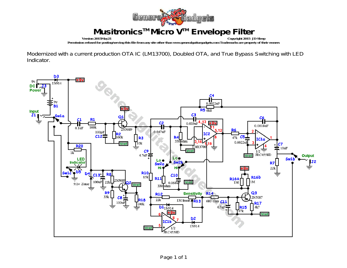
Parts layout
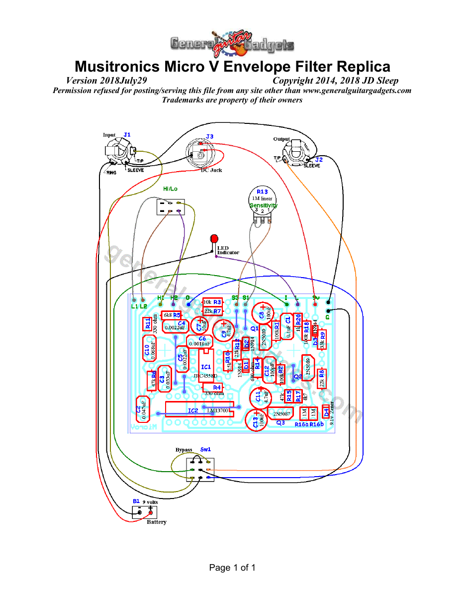
Parts Layout / Wiring Diagram
What you will need
Bill of Materials
Version 2014February24 · Copyright 2014 JD Sleep · Permission refused for posting/serving this file from any site other than www.generalguitargadgets.com · Trademarks are property of their owners
Resistors
| Resistor ID | Value | 3-band Marking | 4-band Marking |
|---|---|---|---|
| R1 | 100k | brown-black-yellow | brown-black-black-orange |
| R2 | 100k | brown-black-yellow | brown-black-black-orange |
| R3 | 10k | brown-black-orange | brown-black-black-red |
| R4 | 330 ohm | orange-orange-brown | orange-orange-black-black |
| R5 | 6k8 (6.8k) | blue-gray-red | blue-gray-black-brown |
| R6 | 47k | yellow-violet-orange | yellow-violet-black-red |
| R7 | 22k | red-red-orange | red-red-black-red |
| R8 | 22k | red-red-orange | red-red-black-red |
| R9 | 33k | orange-orange-orange | orange-orange-black-red |
| R10 | 15k | brown-green-orange | brown-green-black-red |
| R11 | 330 ohm | orange-orange-brown | orange-orange-black-black |
| R12 | 22k | red-red-orange | red-red-black-red |
| R13 (Potentiometer Sensitivity Control) | 1M Linear | ||
| R14 | 680 ohm | blue-gray-brown | blue-gray-black-black |
| R15 | 47k | yellow-violet-orange | yellow-violet-black-red |
| R16a | 1M | brown-black-green | brown-black-black-yellow |
| R16b | 1M | brown-black-green | brown-black-black-yellow |
| R17 | 4k7 (4.7k) | yellow-violet-red | yellow-violet-black-brown |
| R18 | 100k | brown-black-yellow | brown-black-black-orange |
| R19 | none | ||
| R20 | 1k | brown-black-red | brown-black-black-brown |
Capacitors
| Capacitor ID | Value | Type | Possible Marking |
|---|---|---|---|
| C1 | 0.1µF | Film | 104 |
| C2 | 0.047µF | Film | 473 |
| C3 | 0.033µF | Film | 333 |
| C4 | 0.0022µF | Film | 222 |
| C5 | 0.0022µF | Film | 222 |
| C6 | 0.0018µF | Film | 182 |
| C7 | 10µF | Aluminum Electrolytic | 10µF |
| C8 | 100µF | Aluminum Electrolytic | 100µF |
| C9 | 4.7µF | Aluminum Electrolytic | 4.7µF |
| C10 | 0.068µF | Film | 683 |
| C11 | 4.7µF | Aluminum Electrolytic | 4.7µF |
| C12 | 100pF | Ceramic or Film | 101 (or 100pF) |
| C13 | 100µF | Aluminum Electrolytic | 100µF |
Potentiometers
| Part ID | Value | Type |
|---|---|---|
| R13 - Sensitivity Control | 1M | Linear Taper |
Other
| Part ID | Part Name |
|---|---|
| IC1 | RC4558D or other dual opamp |
| IC2 | LM13700 |
| D1, D2, D3, | 1N914 Diodes |
| Q1, Q2 | 2N5089 (or 2N5088) |
| Q3 | 2N5087 |
| D4 | 9.1v Zener Diode |
| D5 | LED |
| J1 | Stereo quarter-inch jack |
| J2 | Mono quarter-inch jack |
| J3 | DC Jack |
| B1 | 9 volt battery (not included in the Kit) |
| Sw1 | Heavy Duty 3PDT foot switch |
| Sw2 (Hi/Lo Switch) | DPDT on-on toggle switch 9v battery snap, Printed Circuit Board, 24 gauge stranded wire, Enclosure, Knobs |
How to build it
Instructions
Version 2018July2018 · Copyright 2014, 2018 JD Sleep · Permission refused for posting/serving this file from any site other than www.generalguitargadgets.com · Trademarks are property of their owners
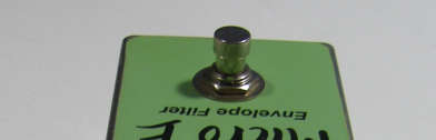
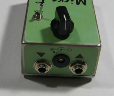
This is a replica of the Musitronics™ Micro V Envelope Filter. Use the project documents provided, starting with the General Build Instructions. Follow the layout diagram for part placement and wiring. The first thing to notice is that some of the diodes and resistors “stand on end”. D1, D2, D3, D4, R11, R15, R16a, R16b, R17 and R20 all stand on end. You should bend one of the component leads all the way over so that you have 2 leads pointing down, then insert it in the part placement. Be careful with these components, make sure they are standing up straight and don't get bent over and short against a nearby component. There are 7 “jumpers” on this PCB. If you have a General Guitar Gadgets PCB, these “jumpers” are built in to the top layer of the PCB and you don't need to add anything. You can ignore the jumpers and the pads at the ends of the jumpers. If you etch the PCB yourself, you will add jumpers to those positions. The kit comes with IC sockets, we would strongly suggest that you use the sockets for the ICs. Comments and questions are welcome and can be sent to:
[email protected] Here is a chart of voltages taken at the IC pins. This information can be used to help you find and fix problems if your Micro 5 doesn't work when you test it. These are approximate voltages, if yours are within 0.5 volt variance, you are probably okay.
Component
Location
9 volt power supply IC1
IC1
Voltage
9.3v
Pin 1
4.5v
Pin 2
4.5v
Pin 3
4.5v
Pin 4
0v
Pin 5
4.5v
Pin 6
4.5v
Pin 7
4.3v
Pin 8
8.2v
Pin 1
1.1v
Pin 2
0v
Pin 3
4.5v
Pin 4
4.5v
Pin 5
4.5v
Pin 6
0v
Pin 7
0v
Pin 8
0v
Pin 9
0.2v
Pin 10
0v
Pin 11
8.2v
Pin 12
4.5v
Q1
Q2
Q3
Pin 13
4.5v
Pin 14
4.5v
Pin 15
0v
Pin 16
1.1v
Collector
8.8v
Base
4.6v
Emitter
4.1v
Collector
8.8v
Base
5.6v
Emitter
4.7v
Collector
1.1v
Base
4.7v
Emitter
4.8v
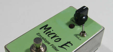
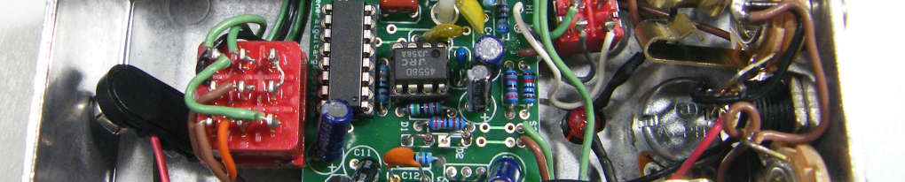
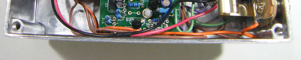
Here's a view of the inside of the completed Musitronics™ Micro V replica in the 125B enclosure.

More about this project
Notes, sounds and related links

Ready to build? We have the kit.
Buy a Micro V Complete Kit. Includes all the parts and materials you need to build one, all for about the price you would pay for a PCB and parts. 
Would you like a Ready to Solder Circuit Board for this project? Note: If you buy the kit, the Ready-to-Solder Printed Circuit Board (RTS PCB) is included in the kit. You do not need to purchase this Ready to Solder Circuit Printed Board if you buy the kit.