Project ITS8 · Overdrive
Ibanez™ Tube Screamer™ Replica
The ITS8 is a faithful replica of the Ibanez™ TS808™ Tube Screamer™, the mid-focused overdrive heard on countless records from Stevie Ray Vaughan onward. Build it from our complete kit (from $55, every part included) or the bare PCB, with free schematics and a six-page modification guide covering TS9™ values, Keeley™ mods and a switchable diode clipper.
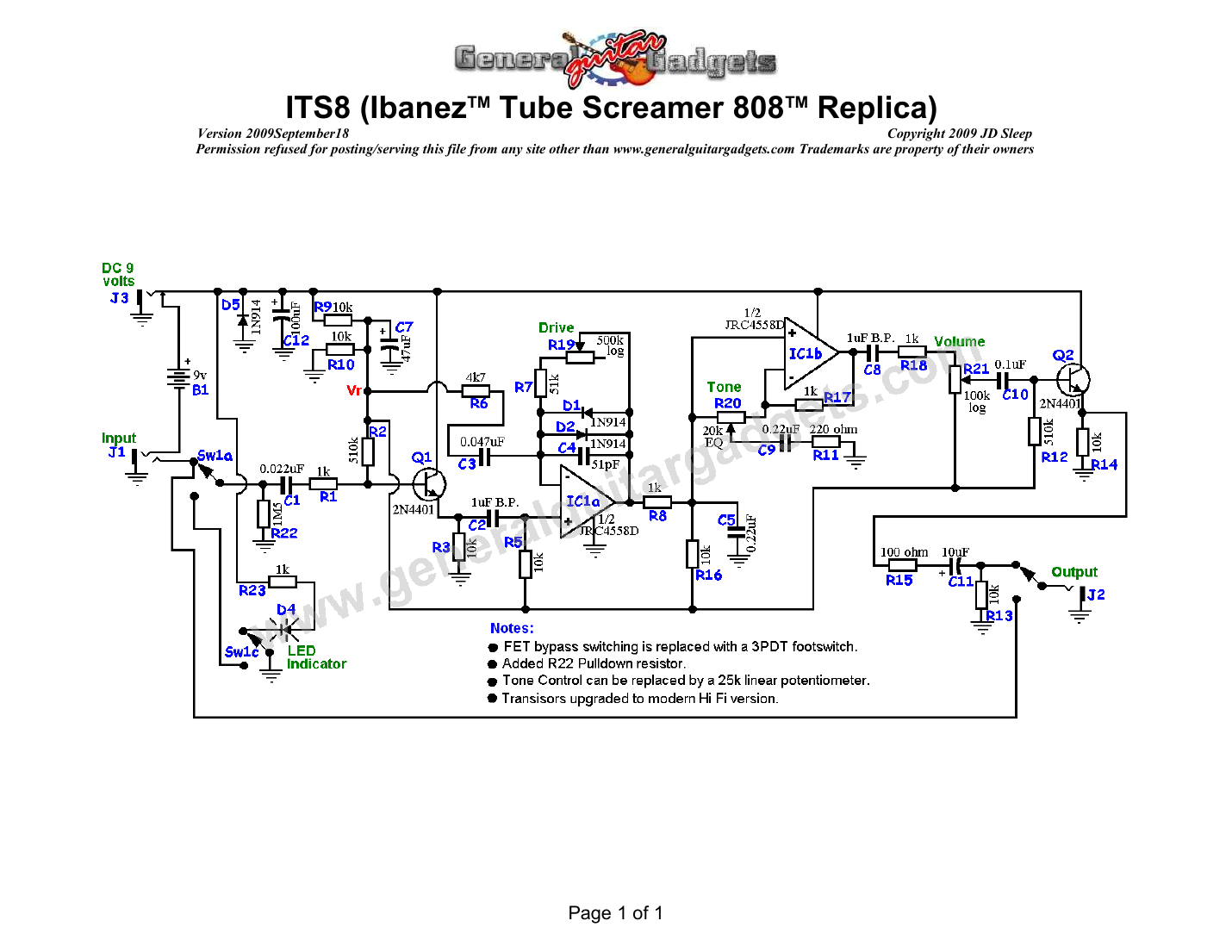
The ITS8 is a replica of the Tube Screamer™ 808 overdrive. This replica does not include the FET switching circuit of the original, it uses a true (total) bypass switch with an LED indicator circuit attached. The switching circuit has no effect on the sound of the stompbox. The layout is designed to accommodate several variations and modifications. Be sure to check out the Modifications file.
Trademarks used here belong to their owners and NOT General Guitar Gadgets

Project files
Everything you need to build it
ITS8 Ready-For-Transfer Printed Circuit Board Layout - For use only if you are a complete DIY person who wants to etch and drill your own PCB. Otherwise, we recommend you ignore this PCB mask and buy the Ready-to-Solder Printed Circuit Board or Complete Kit from the links below.
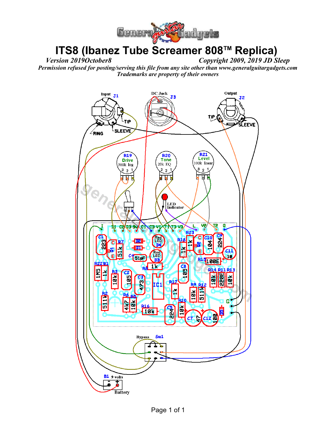
Parts layout
Parts Layout / Wiring Diagram
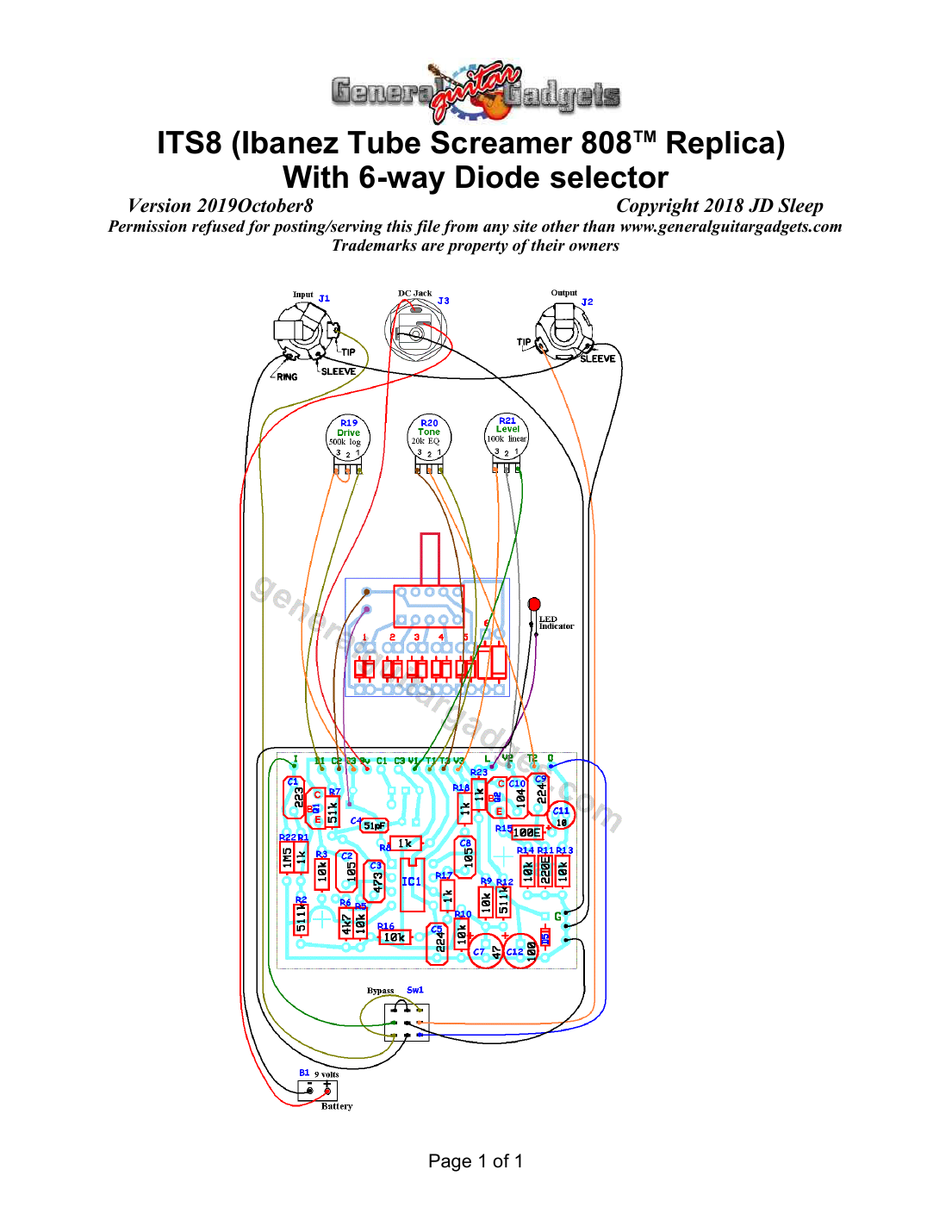
Here is a diagram with the modification of a 6-way diode selector switch
What you will need
Bill of Materials
Version 2009May26 · Copyright 2007 JD Sleep · Permission refused for posting/serving this file from any site other than www.generalguitargadgets.com · Trademarks are property of their owners
Resistors
| Resistor ID | Value | 3-band Marking | 4-band Marking |
|---|---|---|---|
| R1 | 1k | brown-black-red | brown-black-black-brown |
| R2 | 510k (511k Metal Film) | green-brown-yellow | green-brown-brown-orange |
| R3 | 10k | brown-black-orange | brown-black-black-red |
| R4 | None | ||
| R5 | 10k | brown-black-orange | brown-black-black-red |
| R6 | 4k7 (4.7k) | yellow-violet-red | yellow-violet-black-brown |
| R7 | 51k | green-brown-orange | green-brown-black-red |
| R8 | 1k | brown-black-red | brown-black-black-brown |
| R9 | 10k | brown-black-orange | brown-black-black-red |
| R10 | 10k | brown-black-orange | brown-black-black-red |
| R11 | 220 ohm | red-red-brown | red-red-black-black |
| R12 | 510k (511k Metal Film) | green-brown-yellow | green-brown-brown-orange |
| R13 | 10k | brown-black-orange | brown-black-black-red |
| R14 | 10k | brown-black-orange | brown-black-black-red |
| R15 | 100 ohm | brown-black-brown | brown-black-black-black |
| R16 | 10k | brown-black-orange | brown-black-black-red |
| R17 | 1k | brown-black-red | brown-black-black-brown |
| R18 | 1k | brown-black-red | brown-black-black-brown |
| R22 | 1M5 (1.5M) | brown-green-green | brown-green-black-yellow |
| R23 | 1k | brown-black-red | brown-black-black-brown |
Capacitors
| Capacitor ID | Value | Type | Possible Marking |
|---|---|---|---|
| C1 | 0.022µF | Film | 223 |
| C2 | 1µF | Film | 105 |
| C3 | 0.047µF | Film | 473 |
| C4 | 51pF | Ceramic or Film | 51 (or substitute 47pF) |
| C5 | 0.22µF | Film | 224 |
| C6 | none | ||
| C7 | 47µF | Aluminum Electrolytic | 47uF |
| C8 | 1µF | Film | 105 |
| C9 | 0.22µF | Film | 224 |
| C10 | 0.1µF | Film | 104 |
| C11 | 10µF | Aluminum Electrolytic | 10uF |
| C12 | 100µF | Aluminum Electrolytic | 100uF |
Potentiometers
| Part ID | Value | Type |
|---|---|---|
| R19 - Drive Control | 500k | Log (or Audio) Taper |
| R20 - Tone Control | 20k | EQ Taper (or substitute 25k linear) |
| R21 - Level Control | 100k | Linear Taper |
Other
| Part ID | Part Name |
|---|---|
| IC1 | JRC4558D or other dual opamp |
| D1 | 1N914 |
| D2 | 1N914 |
| D2b | 1N914 (optional, for asymmetric clipping) |
| D3 | LED |
| D4 | LED |
| D5 | 1N914 |
| Q1 | NPN bipolar junction transistor |
| Q2 | NPN bipolar junction transistor |
| J1 | Stereo quarter-inch jack |
| J2 | Mono quarter-inch jack |
| J3 | DC Jack |
| B1 | 9 volt battery (not included in the Kit) |
| Sw1 | Heavy Duty 3PDT foot switch |
| 9v battery snap, Printed Circuit Board, 24 gauge stranded wire, Enclosure, Knobs |
Examples of other NPN bipolar junction transistors:
- 2SC1815 (original) – Has a different Pin format than the PCB uses
- 2N3904
- 2N4401
- 2N5088
- MPSA18
- many others
Includes all the parts and materials you need to build one, all for about the price you would pay for a PCB and parts.
How to build it
Instructions
Version 2019November20 · Copyright 2013, 2019 JD Sleep · Permission refused for posting/serving this file from any site other than www.generalguitargadgets.com · Trademarks are property of their owners
This is a replica of the famous Ibanez™ Tube Screamer™ 808 referred to as ITS8 in these documents. One of the best and most well-known guitar overdrive sounds in the world.
Use the project documents provided, starting with the General Build Instructions. Read the Modifications Instructions file before you start, you may get some ideas that you want to use right from the start.
Generally speaking, the type of transistors used on the input and output buffer sections are not important to the sound. Use one of the types listed in the bill of materials or any NPN transistor that is similar to those listed. There is nothing magical about the sound of the original 2SC1815 transistors, in fact they are very "ordinary" transistors. The kits come with 2N4401 transistors, these are very good substitutes for the originals. Please Note: The layout is designed for transistors with a "EBC" pin format. If you use the 2SC1815 you'll have to twist the middle pin out to the side to get it to fit in the correct orientation.
The Tone Control potentiometer on the original is a 20k with an "EQ" taper. A 25k linear pot can be substituted with fairly good results. The kits come with the 20k "EQ" taper pot that is similar to the original units and a much better taper than the 25k linear.
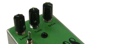
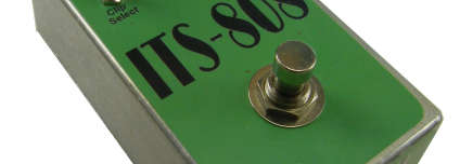


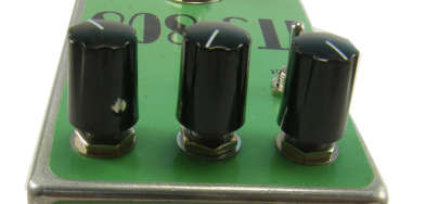
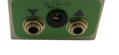
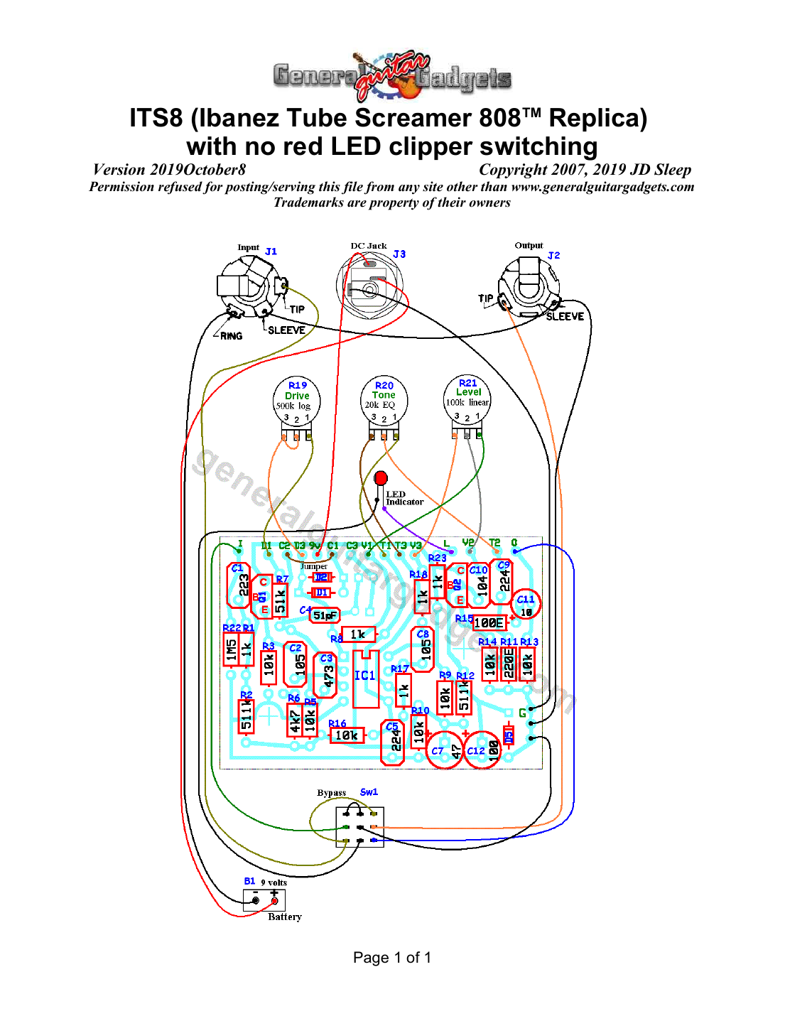
The PCB is designed to use two different "clipping devices" (diodes & red LEDs) that can be switched for different distortion sounds. There is also a diagram available that shows how to install a jumper if you choose to just use the original clipper configuration with no switching. Please Note: it is normal for different clipping components to cause large variations in the overall volume of the distortion pedal. This is true for all distortion pedals that use diode type clippers. This clipper switch will cause volume variations as you switch to different settings.
D5 is optional, it is there to prevent reverse polarity power from destroying the IC. If you decide not to install D5, do not put a jumper in place of D5, just leave it blank. C12 is a power supply filter cap and is also somewhat optional. If you plan on only using battery power, you probably don't need C12. Again, if you don't install C12, do not install a jumper, leave it blank. If you have D5 installed and you do ever zap the unit with reverse power, hopefully all you have to do to fix it is replace or remove D5.
Here's an inside view of the unit we built to show our construction details.




Voltage chart
Here is a chart of voltages taken at the IC and transistor pins. This information can be used to help you find and fix problems if your ITS8 doesn't work when you test it. The voltages are approximate, you may not get these exact readings, but they should be somewhere close.
| Component | Location | Voltage |
|---|---|---|
| 9 volt power supply | 9v | |
| IC | IC Pin 1 | 4.5v |
| IC Pin 2 | 4.5v | |
| IC Pin 3 | 4.5v | |
| IC Pin 4 | 0v | |
| IC Pin 5 | 4.5v | |
| IC Pin 6 | 4.5v | |
| IC Pin 7 | 4.5v | |
| IC Pin 8 | 9v | |
| Q1 | Collector | 9v |
| Base | 3.0v | |
| Emitter | 2.5v | |
| Q2 | Collector | 9v |
| Base | 3.0v | |
| Emitter | 2.5v |
Comments and questions are welcome and can be sent to [email protected]
Questions
Frequently asked questions
Is this the TS808™ or the TS9™ circuit?
The board is a TS808™ replica. The TS9™ differs only in two output-stage resistor values, which are listed in the modification guide, so you can build either.
What's the difference between the kit and the PCB?
The complete kit has the board plus every part, pot, jack, switch and LED, with an optional pre-drilled enclosure. The PCB is the bare board for builders who source their own parts.
What mods can I add?
Keeley™-style changes for more bass and gain, an asymmetric clipping diode, a diode-lift switch that turns the pedal into a clean boost, and a 6-way clipper selector (silicon, LED and more). All are in the free PDF.
How hard is the build?
A good second or third project: about 40 parts, one IC, no trimmers. Allow an evening, and read the General Build Instructions first.
Make it your own
Modification Instructions
Version 2007August29 · Copyright 2006 JD Sleep · Permission refused for posting/serving this file from any site other than www.generalguitargadgets.com · Trademarks are property of their owners
This document describes some of the many modifications you can make to the ITS8.
Asymmetric Clipping Modification
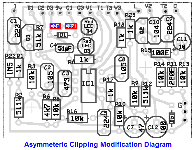
The first modification is to add "asymmetric clipping". This is reported to make the distortion sound "more tube-like". Try it and judge for yourself, it will give a different kind of distortion that may be more to your liking. Just replace the one diode, D2, with two diodes as shown in the diagram below. The layout has been designed to be able to put 2 diodes in this position standing on end as shown in the instructions photo.
Clipper Modifications
The base build of this project includes a toggle switch and clipping parts to switch between using silicon diodes (1N914) and red LED clippers. This is a great way to get a couple of different distortion sounds from the same box. There are many other electronic devices that can be used as clippers here in positions of the diodes or LED. Some choices are:
- Germanium Diode
- Silicon or any other type of diode
- LED (other colors)
- Transistor
- MOSFET transistor
and many more. You can use combinations of any clipping devices and two or more in series, asymmetric arrangements, etc.
If you want more than 2 clipping options you can install a rotary switch and mount more clipping devices on the switch or use a small piece of perfboard or other material to mount clippers on another small circuit board.
AMZ Fat Modification
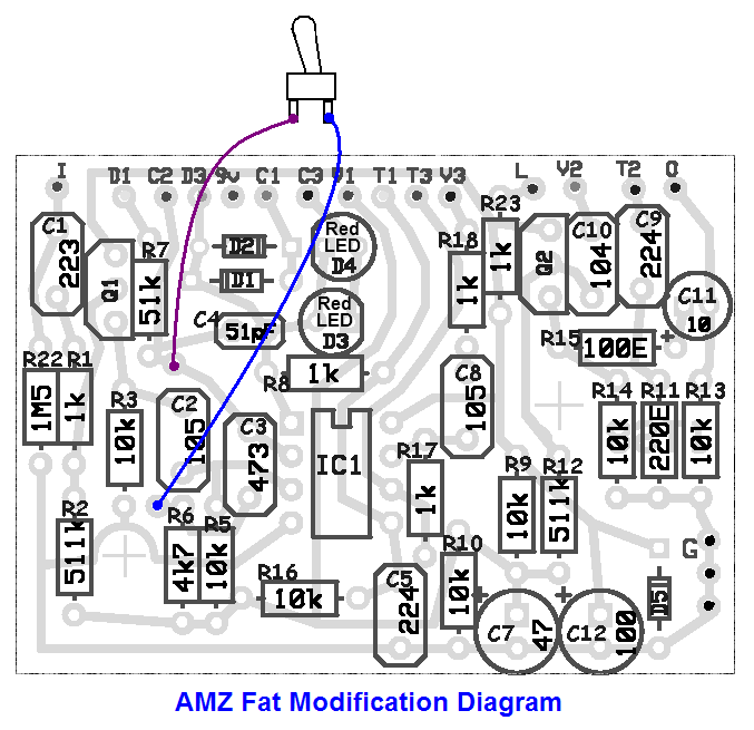
This modification is from the www.amzfx.com site. It is a switch that bypasses C3 and gives more boost and bass response to the sound. The PCB boards and kits we sell already have the holes for this modification.
Keeley™ 808 Reissue Modifications
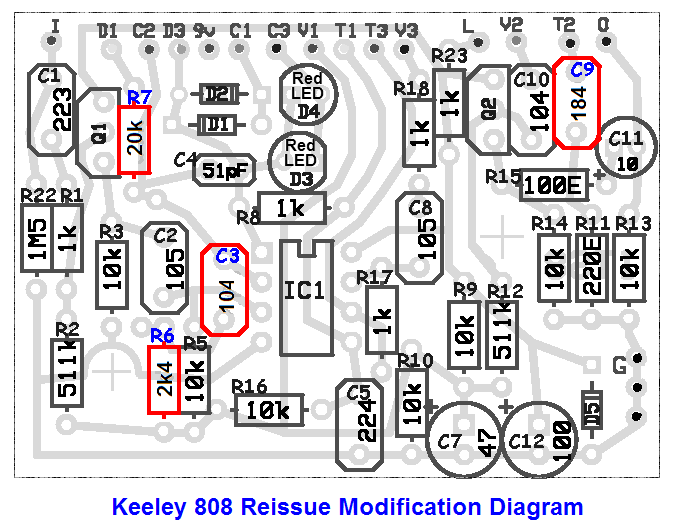
According to the text on the Robert Keeley™ site, as far as we can tell, these are the modifications they do for the Ibanez™ TS 808™ reissues. The other mods Keeley™ lists are not applicable to this project or are covered by other mods listed here. These mods should sound excellent on this project as well. The modifications will give better bass response, more distortion on the higher Drive settings and maybe a better sound on the lower drive settings. The modifications are:
- R6 replace 4k7 resistor with 2k4 resistor
- R7 replace 51k resistor with 20k resistor
- C3 replace 0.047uF with 0.1uF capacitor
- C9 replace 0.22uF with 0.18uF capacitor
Diode Lift Modification
If you disconnect the diode clippers from the feedback loop of the first stage of the circuit, the ITS8 circuit can be used as a booster! The easy way to do this is to use an on-off-on style SPDT toggle switch for the diode clipper selector switch. Then the two sets of diodes can still be selected and the center off position allows for a booster option. The Kit comes with the on-off-on style toggle switch, so this modification is included in the kit.
Note that if you crank the drive up with the clippers lifted, you will get some very nasty distortion, you may or may not like it. To get the mostly clean boost, the drive is set to the lower settings and a mostly clean boost can be achieved. The boosted sound may have just a bit of distortion, this can be an excellent booster application for some rigs.
Expensive Boutique Modifications
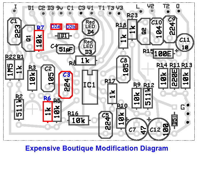
These are the modifications for a well known very expensive boutique TS type overdrive circuit. We emphasize the word circuit, since you won't get the fancy paint job nor the "mystique" of one of the original units. Use the diode switching with diode lift on-off-on switch as shown above, also use the asymmetric clipping modification as shown above. Then use the part values shown below. Replace the Drive pot with a 1 Meg Log pot. This mod uses the same principles of increased gain as the Keeley™ mod and the AMZ Fat mod. Save yourself a few hundred dollars and enjoy!
Other Modifications
IC Modifications
Try different ICs in your ITS8. The JRC4558D is supposed to be the magic IC, but other dual opamps will sound excellent and may suit your tastes better. Any dual opamp with the same standard pin layout is worth a try.
TS9™
- R13100k
- R15470
TS10™
- R4220 ohms
- R13100k
- R15470
Aron Nelson Modification Suggestions
- R61K
- C30.47uF
- C5jumper
- R19Replace the 500k log potentiometer with a 1M log potentiometer
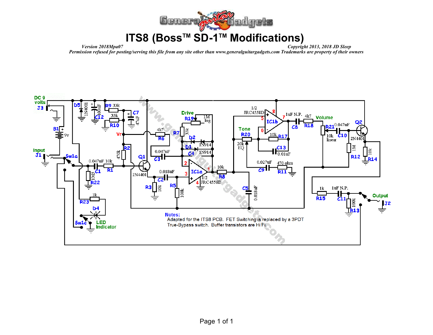
Boss™-SD1™ Mods (according to the GM Arts schematic)
To make this circuit similar to a Boss™ SD1™, substitute these values in the parts layout:
- D1, D2a & D2b1N916 diodes
- C10.047uf
- R110k
- R2470k
- R4jumper
- C20.018uF
- C50.018uF
- C60.01uF
- C90.027uF
- R810k
- R1710k
- R184.7k
- R191M pot
- R2110k pot
Solder a 33k resistor in series to leg 1 of the 1M pot (R19)
Same board, more builds
Also builds on the ITS8 PCB
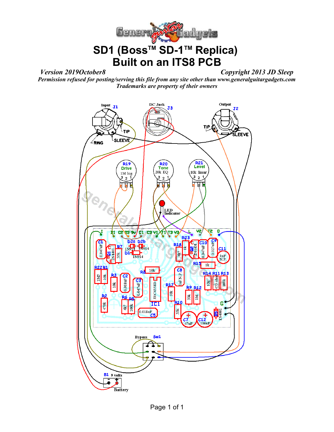
Boss™ SD-1™
Here's an adaptation of the Boss™ SD-1™ that can be built on the ITS8 PCB.
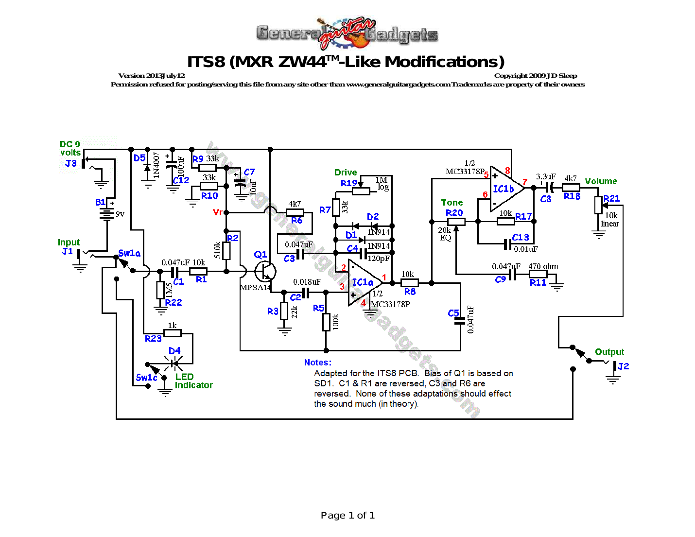
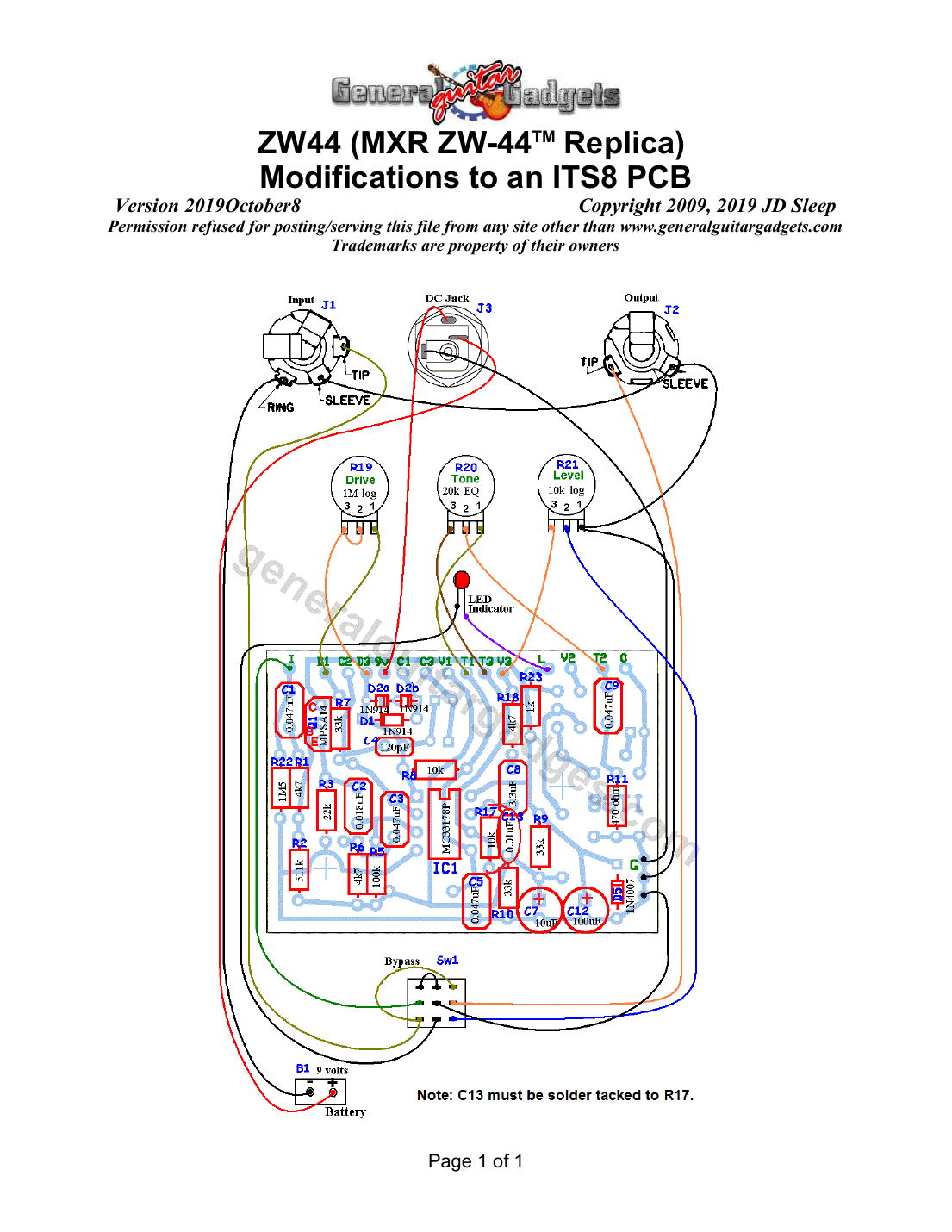
MXR™ ZW-44™
Here's an adaptation of the MXR™ ZW-44™ that can be built on the ITS8 PCB. There are some very minor adaptations, the input buffer is not biased like the ZW-44™, but like an SD1™. We don't think that makes much difference in the sound.
Further reading
Related schematics and links
Here's some related schematics.
- Original TS-808™ Schematic Thanks to Steve Cerutti.
- Overdone FullDive 1 Schematic Thanks to Steve Cerutti.
- Overdone FullDive 2 Schematic Thanks to Steve Cerutti.


Here are more links related to the Tube Screamer™:
- The Technology of the Tube Screamer™ from GEOFEX. (note: the Geofex links on this page go to an external site that does not use a secure HTTPS connection) Even if you don't understand any of the electronic technology, it'll give you a feel for what you're working with and has great information about modifications to the circuit.
- AMZ Fat Bass for Tube Screamer™ Modifications from AMZ
Ready to build? We have the kit.
Would you like a Ready to Solder Circuit Board for this project? Note: If you buy the kit, the Ready-to-Solder Printed Circuit Board (RTS PCB) is included in the kit. You do not need to purchase this Ready to Solder Circuit Printed Board if you buy the kit.