
Project · Distortion
Way Huge™ Red Llama™
This is a replica of the Way Huge™ Red Llama™. It's a nice little distortion overdrive that is famous for overdriving a tube amp into some wonderful tones. It also has a pretty good overdrive sound on its own that sounds great into a solid state amp or low volumes (not overdriven) tube amp.
The story
About the circuit
Jeorge Tripps started Way Huge™ Electronics in California in the mid-1990s, and the Red Llama™ was one of its first pedals. Inside is not a transistor or an op-amp but a CMOS chip, the CD4049, a hex inverter meant for logic circuits. Run as an amplifier, its stages break up much like an overdriven tube, which is why the Red Llama™ is famous for pushing a tube amp into a warm, touch-sensitive overdrive. The idea goes back to Craig Anderton's 1975 book Electronic Projects for Musicians, where it appeared as the "Tube Sound Fuzz." Way Huge™ closed at the end of the '90s and the originals became collector's pieces before Dunlop revived the brand.
This project at GGG
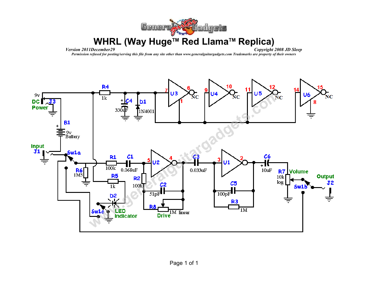
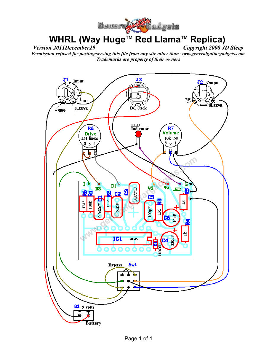
Our WHRL kit follows the Red Llama™, with part values that differ slightly from Anderton's original. It is one of the easiest builds on the site, and a good one for a first or second pedal. The one thing that matters is the chip: it has to be the unbuffered CD4049UB, and that is what the kit includes. It sounds great into a tube amp on the edge of breakup, and good on its own into a clean or solid-state amp. The schematic and layout are below.
What you will need
Bill of Materials
Version 2009May26 · Copyright 2008 JD Sleep · Permission refused for posting/serving this file from any site other than www.generalguitargadgets.com · Trademarks are property of their owners
Resistors
| Resistor ID | Value | 3-band Marking | 4-band Marking |
|---|---|---|---|
| R1 | 100k | brown-black-yellow | brown-black-black-orange |
| R2 | 100k | brown-black-yellow | brown-black-black-orange |
| R3 | 1M | brown-black-green | brown-black-black-yellow |
| R4 | 1k | brown-black-red | brown-black-black-brown |
| R5 | 1k | brown-black-red | brown-black-black-brown |
| R6 (Optional) | 1M5 | brown-green-green | brown-green-black-yellow |
Potentiometers
| Part ID | Value | Type |
|---|---|---|
| R8 - Drive Control | 1M | Linear Taper |
| R7 - Volume Control | 10k | Log Taper |
Capacitors
| Capacitor ID | Value | Type | Possible Marking |
|---|---|---|---|
| C1 | 0.068µF | Film or ceramic | 683 |
| C2 | 51pF | Ceramic | 51 |
| C3 | 0.033µF | Film or ceramic | 333 |
| C4 | 330µF | Aluminum Electrolytic | 330µF |
| C5 | 100pF | Ceramic | 100 or 101 |
| C6 | 10µF | Aluminum Electrolytic | 10µF |
Other
| Part ID | Part Name |
|---|---|
| IC1 | 4049UBN |
| D1 | 1N4001 |
| J1 | Stereo quarter-inch jack |
| J2 | Mono quarter-inch jack |
| J3 | DC Jack |
| B1 | 9 volt battery (not included in the Kit) |
| Sw1 | Heavy Duty 3PDT footswitch 9v battery snap, Printed Circuit Board, 24 gauge stranded wire, Enclosure, knobs |
How to build it
Instructions
Version 2009January26 · Copyright 2008 JD Sleep · Permission refused for posting/serving this file from any site other than www.generalguitargadgets.com · Trademarks are property of their owners
This is the WHRL Overdrive kit (Way HugeTM Red LlamaTM Replica). This Overdrive is an easy to build project that will produce a great "overdriven tube" sound to your guitar signal. The circuit originated from Craig Anderton's excellent book Electronic Projects for Musician. Named "Tube Sound Fuzz" (project 24) Some of the part values are slightly different. Use the project documents provided, starting with the General Build Instructions. Make sure to use an unbuffered version of the 4049 IC. C2 and C5 have hole spacing for caps with lead spacing of 0.1 or 0.2 inch. These are the common spacings for small ceramic caps, and sometimes it's difficult to find them in just one or the other spacing. If you use 0.1 spacing caps, make sure to insert the leads in the top two holes (nearest the edge with the off-board connection pads). The kit includes two 1Meg resistors that you can use as "pull down" resistors if you think you absolutely must have it like the original. The pull down resistor on the output is completely unnecessary since the volume pot on the output provides the pull down needed. There is also space on the PCB for the input and this project uses a 1M5 resistor for that.
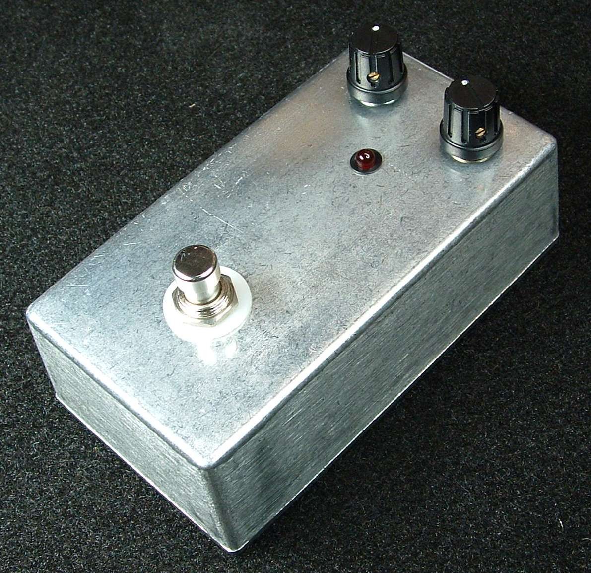
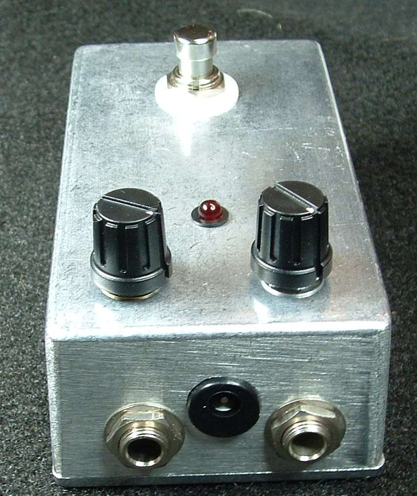
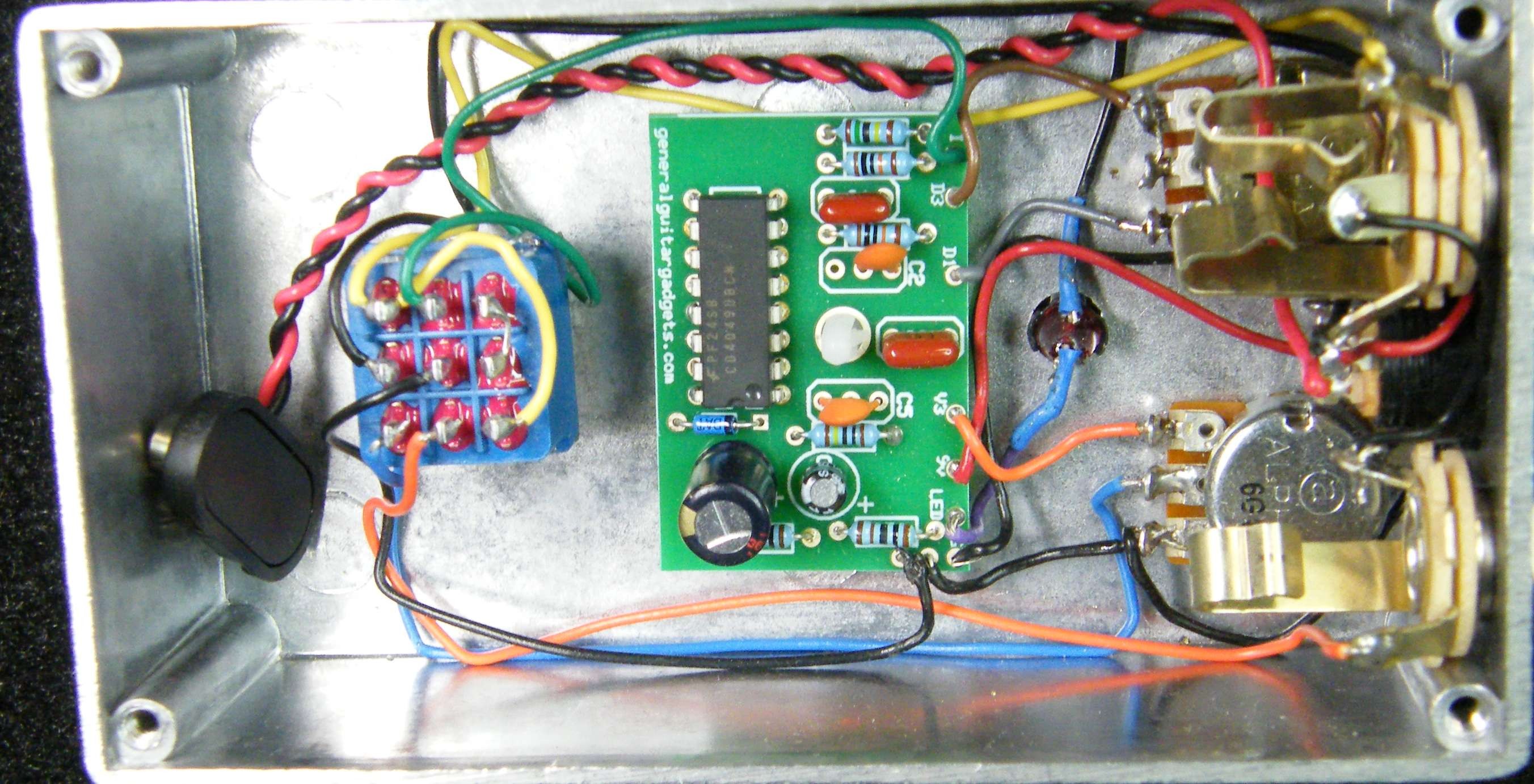
Here's an inside view of the unit we built to give you a real view of the construction.
For trouble shooting purposes, here are the voltages at the IC pins:
Component
Location
9 volt power supply IC1
Voltage
9.5v
IC Pin 1
5.5v
IC Pin 2
2.7v
IC Pin 3
2.7v
IC Pin 4
2.7v
IC Pin 5
2.7v
IC Pin 6
0.01v
IC Pin 7
5.5v
IC Pin 8
0.0v
IC Pin 9
5.5v
IC Pin 10
0.01v
IC Pin 11
5.5v
IC Pin 12
0.01v
IC Pin 13
0.0v
IC Pin 14
5.5v
IC Pin 15
0.01v
IC Pin 16
0.0v
More about this project
Notes, sounds and related links

Ready to build? We have the kit.
Buy a WHRL Complete Kit. Includes all the parts and materials you need to build one, all for about the price you would pay for a PCB and parts.

Would you like a Ready to Solder Circuit Board for this project ?