
Project · Distortion
ProCo™ Rat™
The Rodent is a replica of the ProCo™ Rat™, the distortion pedal that goes from gritty overdrive to full fuzz with one Filter knob. The complete kit is $55 with every part included and ships with the OP07 op-amp used in today's Rats, plus a socket so you can drop in a vintage LM308; the free schematic and wiring diagram are below.
The Rodent is a ProCo™ Rat™ Replica. Thanks to Scott Swartz for his contribution to this project. Trademarks mentioned on this page belong to their owners and NOT General Guitar Gadgets.

The story
About the circuit
The Rat™ came out of ProCo™ Sound in Kalamazoo, Michigan, in 1978, designed by Scott Burnham and Steve Kiraly. An LM308 op-amp provides the gain, a pair of silicon diodes clip the signal hard to ground, and the Filter control is a low-pass that works backwards from what you'd expect: turn it up and the sound gets darker. The result covers everything from a gritty boost to a saturated fuzz, and the LM308's slow slew rate is part of why it sounds the way it does. The big black box has been on records by Jeff Beck, Radiohead, Sonic Youth and Nirvana, and ProCo™ has kept it in production with changes to the chip over the years.
This project at GGG
Our Rat™ replica is called the Rodent, and it came to the site in February 2002 thanks to Scott Swartz, who contributed the project. The kit ships with the OP07 op-amp used in current Rats plus a socket, so you can drop in a vintage LM308 if you find one and hear the difference for yourself. The free schematic and wiring diagram are below, and the Rodent remains one of the most-built distortions on the site.
Project files
Everything you need to build it
Rodent Ready-For-Transfer Printed Circuit Board Layout PDF File - For use only if you are a complete DIY person who wants to etch and drill your own PCB. Otherwise, we recommend you ignore this PCB mask and buy the Ready-to-Solder Printed Circuit Board or Complete Kit from the links below.
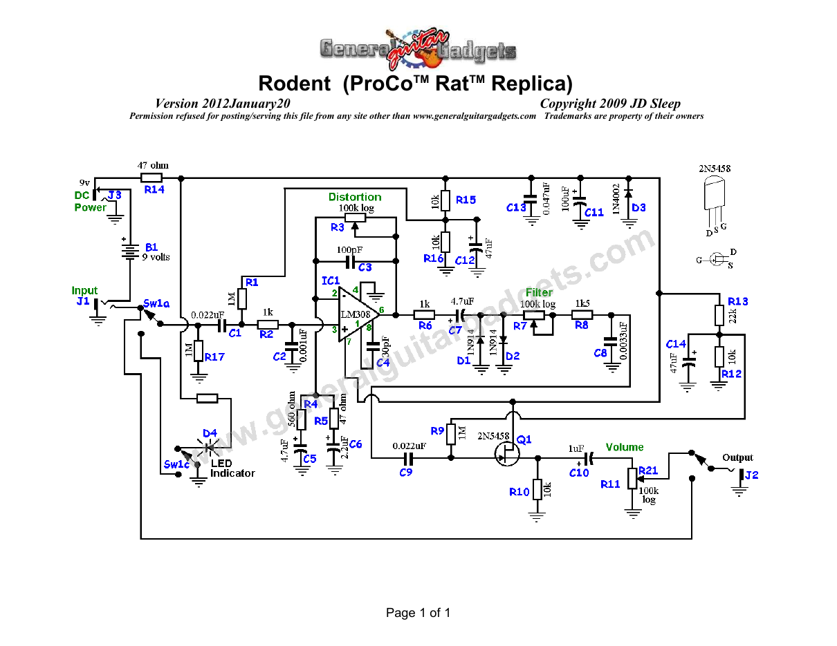
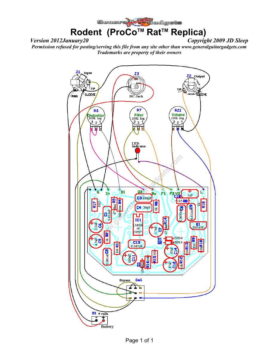
What you will need
Bill of Materials
Version 2013July10 · Copyright 2009 JD Sleep · Permission refused for posting/serving this file from any site other than www.generalguitargadgets.com · Trademarks are property of their owners
Resistors
| Resistor ID | Value | 3-band Marking | 4-band Marking |
|---|---|---|---|
| R1 | 1M | brown-black-green | brown-black-black-yellow |
| R2 | 1k | brown-black-red | brown-black-black-brown |
| R3 (Distortion Control) | 100k Log Potentiometer | ||
| R4 | 560 ohm | green-blue-brown | green-blue-black-black |
| R5 | 47 ohm | yellow-violet-black | yellow-violet-black-gold |
| R6 | 1k | brown-black-red | brown-black-black-brown |
| R7 (Filter Control) | 100k Log Potentiometer | ||
| R8 | 1k5 (1.5k) | brown-green-red | brown-green-black-brown |
| R9 | 1M | brown-black-green | brown-black-black-yellow |
| R10 | 10k | brown-black-orange | brown-black-black-red |
| R11 (Volume Control) | 100k Log Potentiometer | ||
| R12 | 10k | brown-black-orange | brown-black-black-red |
| R13 | 22k | red-red-orange | red-red-black-red |
| R14 | 47 ohm | yellow-violet-black | yellow-violet-black-gold |
| R15 | 10k | brown-black-orange | brown-black-black-red |
| R16 | 10k | brown-black-orange | brown-black-black-red |
| R17 | 1M5 (1.5M) | brown-green-green | brown-green-black-yellow |
| R18 | 1k | brown-black-red | brown-black-black-brown |
Capacitors
| Capacitor ID | Value | Type | Possible Marking |
|---|---|---|---|
| C1 | 0.022µF | Film | 223 |
| C2 | 0.001µF | Film | 102 |
| C3 | 100pF | Ceramic or Film | 101 (or 100pF) |
| C4 | 30pF | Ceramic or Film | 30 |
| C5 | 4.7µF | Aluminum Electrolytic | 4.7uF |
| C6 | 2.2µF | Aluminum Electrolytic | 2.2uF |
| C7 | 4.7µF | Aluminum Electrolytic | 4.7uF |
| C8 | 0.0033µF | Film | 332 |
| C9 | 0.022µF | Film | 223 |
| C10 | 1µF | Aluminum Electrolytic | 1uF |
| C11 | 100µF | Aluminum Electrolytic | 100uF |
| C12 | 47µF | Aluminum Electrolytic | 47uF |
| C13 | 0.047µF | Film | 473 |
| C14 | 47µF | Aluminum Electrolytic | 47uF |
Potentiometers
| Part ID | Value | Type |
|---|---|---|
| R3 - Distortion Control | 100k | Log (or Audio) Taper |
| R7 - Filter Control | 100k | Log (or Audio) Taper |
| R11 - Volume Control | 100k | Log (or Audio) Taper |
Other
| Part ID | Part Name |
|---|---|
| IC1 | LM308 or OP07 opamp (LM208 or other opamp with like slew rate spec can also be used) |
| D1 | 1N914 |
| D2 | 1N914 |
| D3 | 1N4002 (or other diode) |
| D4 | LED |
| Q1 | JFET transistor 2N5458 |
| J1 | Stereo quarter-inch jack |
| J2 | Mono quarter-inch jack |
| J3 | DC Jack |
| B1 | 9 volt battery (Not included in Kit) |
| Sw1 | Heavy Duty 3PDT foot switch 9v battery snap, Printed Circuit Board, 24 gauge stranded wire, Enclosure, Knobs, Rubber Feet, PCB Standoffs |
How to build it
Instructions
Version 2014December30 · Copyright 2009, 2014 JD Sleep · Permission refused for posting/serving this file from any site other than www.generalguitargadgets.com · Trademarks are property of their owners
This is the Rodent Distortion kit, a replica of the ProCo™ Rat™. There were/are several versions of the Rat™. This project and kit is based on an older version of the Rat™ circuit sometimes known as version "B". It does not include a JFET on the input of the circuit as version "A" had. Experimentation has shown the input JFET does not have much effect on the sound and is probably not worth the extra parts to include it in this project.
The Opamp
The original Rat™ used the LM308, which is now obsolete and expensive to buy, though still available from some sources. The datasheet for the LM308 states that the special characteristics of this opamp are very low input bias current, low supply current, and guaranteed drift characteristics, characteristics not normally important to audio. Further checking of the datasheet shows the slew rate of the LM308 (0.15 V/microsecond) is dismal compared to a typical audio opamp, like a TL071, which I think is the key to why it sounds great in the RAT circuit. Comparing the LM308 to both the TL061 and the TL071, the TL opamps sound OK in the Rat™ circuit, they are brighter and more of a heavy metal type of tone, and there is some "plinking" to the attack. The LM308 gives a warmer tone, less treble, and
with a smoother, more tube-like attack, no "plinking". The dismal slew rate may be responsible for this - the opamp simply cannot reproduce the pick attack at high gain. The LM108 or a LM208 should work the same as the LM308, the specs are the same except the 108 and 208 are guaranteed over a wider temperature range. There are also other opamps like the LM10 or the OP-08E with very similar specs. This kit uses the OP07 opamp that is used in the current model Rat™ distortions. We compared the sound of this circuit with the LM308 IC and the OP07 IC and found little or no difference in the sound. Your results may vary, depending on your guitar and rig. For that reason, the kit does include a IC socket, so if you wish to find and purchase a LM308 or other IC on your own and try them out, it will be easy to do. The project also includes a nice little add-on that allows you to set the bias on the JFET. The voltage divider of R12 and R13 sets the voltage on the 1 meg gate resistor, which in turn sets the source voltage. The original had that 1 meg resistor set to ground voltage and if you want your Rodent to be as original, leave R13 blank and use the included 0 ohm resistor (jumper) for R12. This will set the voltage into R9 at ground voltage as original. We recommend the values listed for R12 and R13 as we believe it sounds a little better. Total current consumption of the entire effect is about 3 ma, which means long battery life.
Populating the PCB
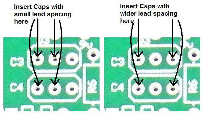
Use the project documents provided, starting with the General Build Instructions. There are a couple of options for populating the small ceramic capacitors. Since they are usually available in two different lead spacings and it's sometimes difficult to source the caps with just the right lead spacing, there are optional lead spacing holes for C3 and C4. See the diagram below for placement.
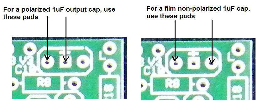
The output capacitor C10 placement is similar. The kit includes a great sounding aluminum electrolytic capacitor, but 1uF film cap can be used if you are sourcing your own parts.
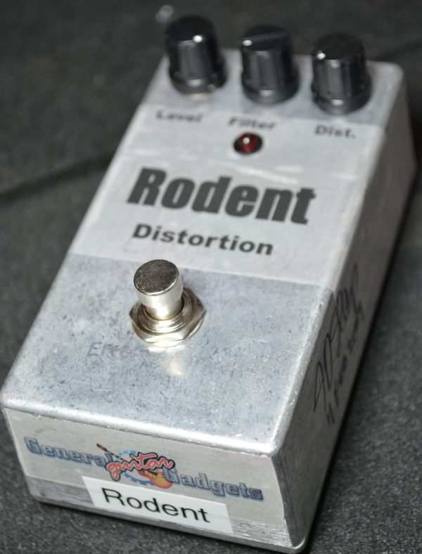
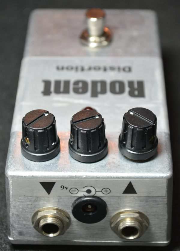
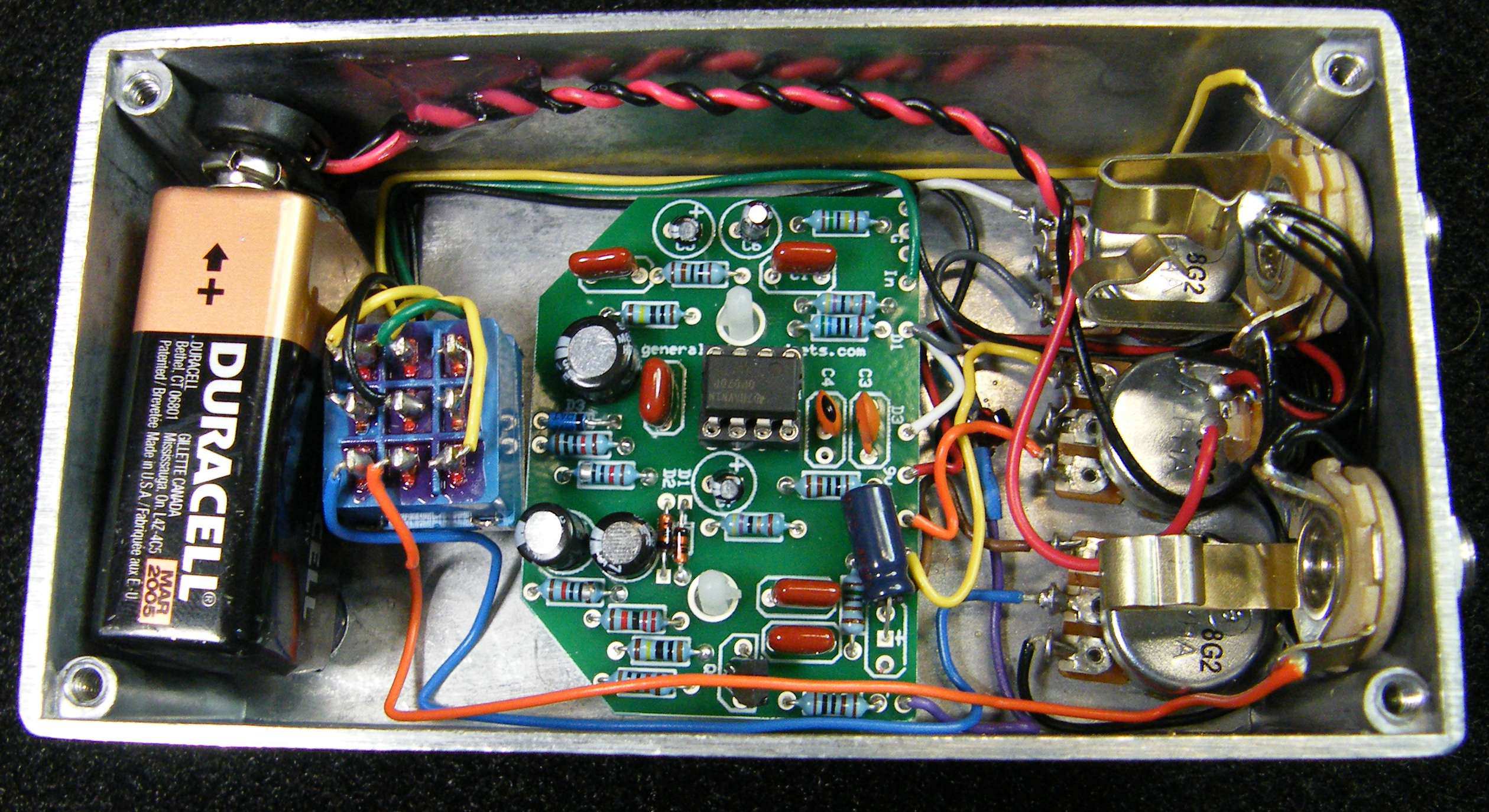
Here's an inside view of the unit we built to give you a real view of our construction.
Here is a chart of voltages taken at the IC pins. Use these voltages as a guideline. You may not get the exact readings listed, but should be somewhere in the area.
Component
Location
9 volt power supply IC1
Voltage
9v
Pin 1
8.4v
Pin 2
4.5v
Pin 3
4.1v
Pin 4
0v
Pin 5
0v
Pin 6
4.5v
Pin 7
9v
Pin 8
4.6v
Questions
Frequently asked questions
OP07 or LM308?
The kit's OP07 is what current Rats use and sounds nearly identical in this circuit. The socket takes an LM308 if you want the original chip; a TL071 gives a brighter, more aggressive sound.
Which Rat™ version is this?
The 1980s circuit ('version B'), without the input JFET of the earliest units; the JFET had almost no effect on the sound.
Can I make it a Turbo Rat™?
Yes: swap the two 1N914 clipping diodes for red LEDs for the louder, more open Turbo sound. The diodes sit on the board and are easy to change.
How hard is the build?
Easy: one op-amp, one JFET, about 35 parts and no trimmers. A good first pedal.
More about this project
Notes, sounds and related links


Here are some other ProCo™ Rat™ schematics from the archives.


Ready to build? We have the kit.
Buy a ProCo™ Rat™ Complete Kit. Includes all the parts and materials you need to build one, all for about the price you would pay for a PCB and parts.
d Would you like a Ready to Solder Circuit Board for this project? Note: If you buy the kit, the Ready-to-Solder Printed Circuit Board (RTS PCB) is included in the kit. You do not need to purchase this Ready to Solder Circuit Printed Board if you buy the kit.