
Project · Distortion
MBB (Marshall™ BluesBreaker™ Replica)
The MBB is a replica of the original black Marshall™ Bluesbreaker™, the low-gain overdrive from the late 1980s that boutique builders copied into the King of Tone and Morning Glory. The complete kit is $55 with every part included and builds true bypass by default; the free schematics and layouts below cover the original wiring, the King of Tone and Morning Glory modifications, and a clean-boost setting.
This is a Vintage Marshall™ BluesBreaker™ replica pedal project. All trademarks mentioned here belong to their owners and not to General Guitar Gadgets. This is the circuit for the original black unit from the 1980’s, not any of the later (thought to be inferior) versions. It's a classic pedal and, as the name implies, a great tone for blues players.
Project files
Everything you need to build it
MBB Ready-For-Transfer to Printed Circuit Board - For use only if you are a complete DIY person who wants to etch and drill your own PCB. Otherwise, we recommend you ignore this PCB mask and buy the Ready-to-Solder Printed Circuit Board or Complete Kit from the links below.
Schematic
Schematic
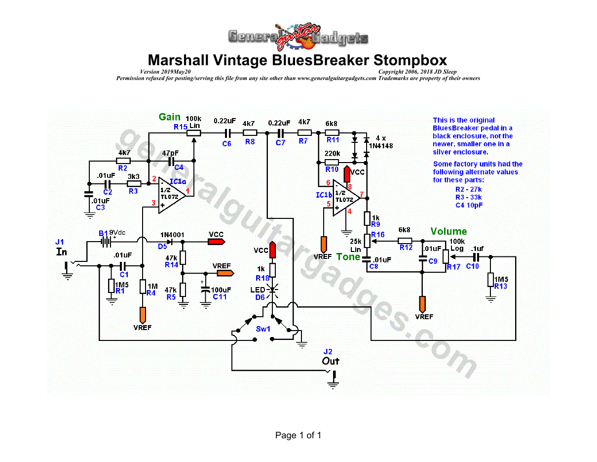
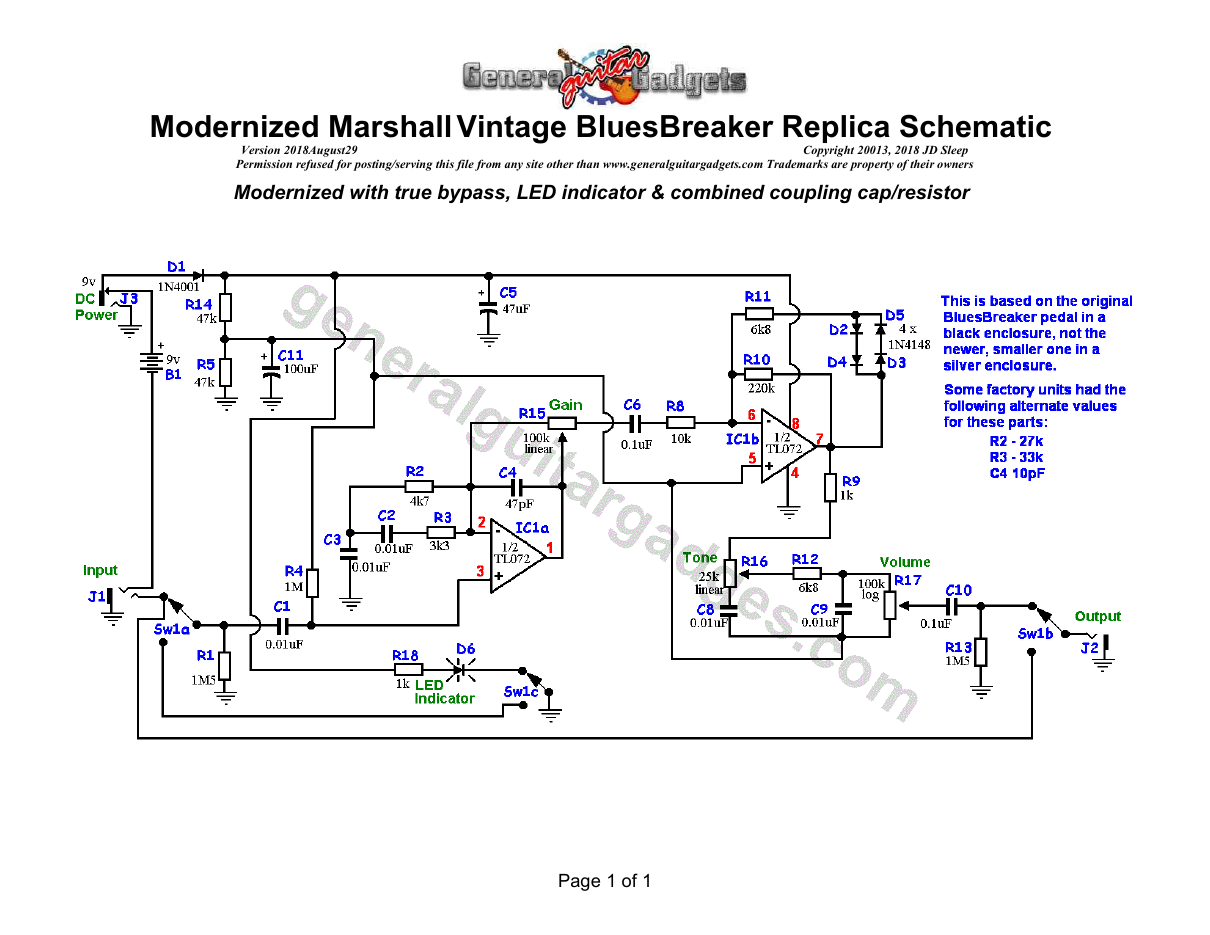
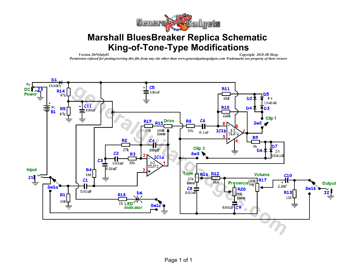
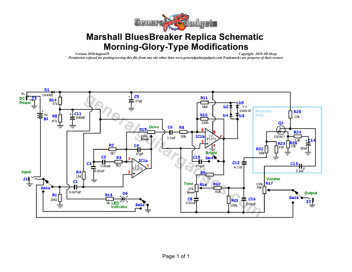
Parts layout
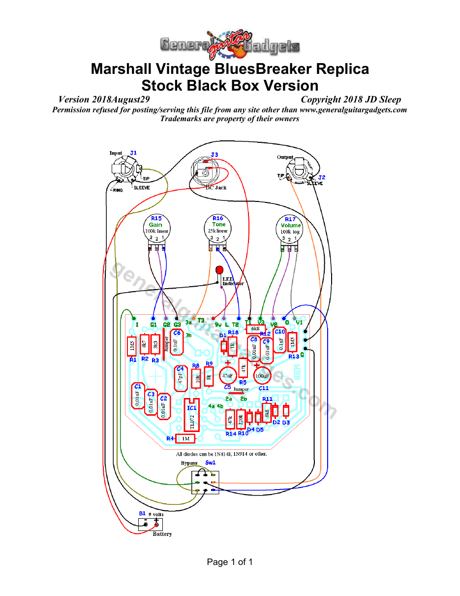
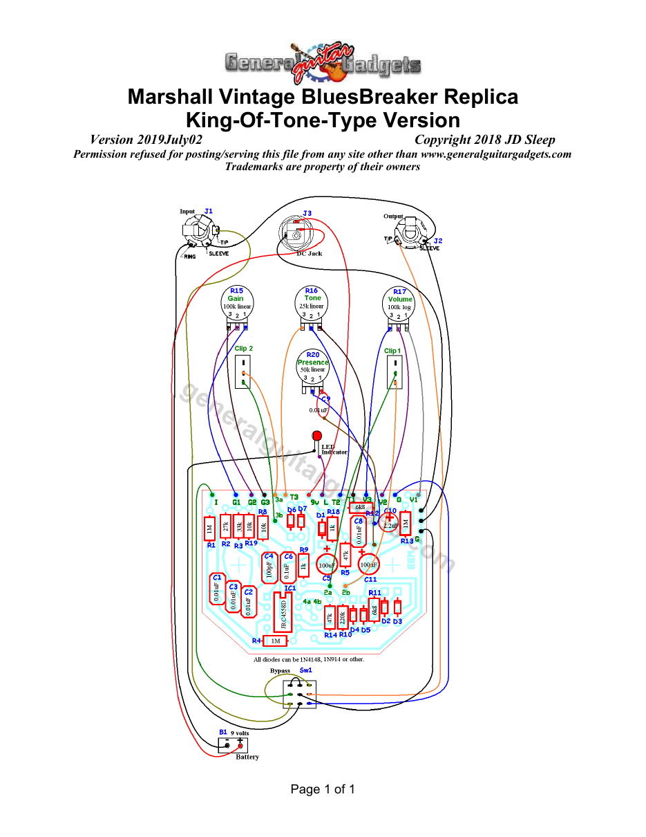
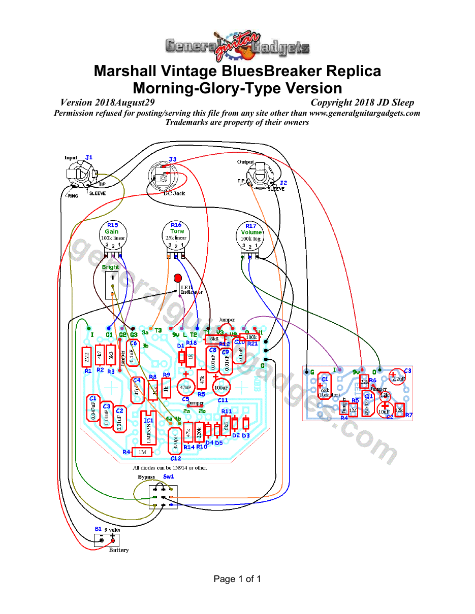
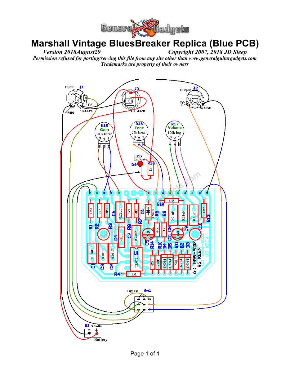
Parts Layout / Wiring Diagram
What you will need
Bill of Materials
Version 2019July17 · Copyright 2007, 2019 JD Sleep · Permission refused for posting/serving this file from any site other than www.generalguitargadgets.com · Trademarks are property of their owners
Resistors
| Resistor ID | Value | 3-band Marking | 4-band Marking |
|---|---|---|---|
| R1 | 1M5 (1.5M) | brown-green-green | brown-green-black-yellow |
| R2 | 4k7 (4.7k) | yellow-violet-red | yellow-violet-black-brown |
| R3 | 3k3 (3.3k) | orange-orange-red | orange-orange-black-brown |
| R4 | 1M | brown-black-green | brown-black-black-yellow |
| R5 | 47k | yellow-violet-orange | yellow-violet-black-red |
| R6 | None | ||
| R7 | None | ||
| R8 | 10k | brown-black-orange | brown-black-black-red |
| R9 | 1k | brown-black-red | brown-black-black-brown |
| R10 | 220k | red-red-yellow | red-red-black-orange |
| R11 | 6k8 (6.8k) | blue-gray-red | blue-gray-black-brown |
| R12 | 6k8 (6.8k) | blue-gray-red | blue-gray-black-brown |
| R13 | 1M5 (1.5M) | brown-green-green | brown-green-black-yellow |
| R14 | 47k | yellow-violet-orange | yellow-violet-black-red |
| R15 (Gain) | 100k Linear Potentiometer | ||
| R16 (Tone Control) | 25k Linear Potentiometer | ||
| R17 (Volume Control) | 100k Log Potentiometer | ||
| R18 | 1k | brown-black-red | brown-black-black-brown |
Capacitors
| Capacitor ID | Value | Type | Possible Marking |
|---|---|---|---|
| C1 | 0.01µF | Film | 103 |
| C2 | 0.01µF | Film | 103 |
| C3 | 0.01µF | Film | 103 |
| C4 | 47pF | Ceramic or Film | 47pF |
| C5 | 47µF | Aluminum Electrolytic | 47µF |
| C6 | 0.1µF | Film | 104 or µ1xxxx |
| C7 | None | ||
| C8 | 0.01µF | Film | 103 |
| C9 | 0.01µF | Film | 103 |
| C10 | 0.1µF | Film | 104 or µ1xxxx |
| C11 | 100µF | Aluminum Electrolytic | 100µF |
Potentiometers
| Part ID | Value | Type |
|---|---|---|
| R15 - Gain Control | 100k | Linear Taper |
| R16 - Tone Control | 25k | Linear Taper |
| R13 - Volume | 100k | Log (or Audio) Taper |
Other
| Part ID | Part Name |
|---|---|
| IC1 | TL072 or other dual opamp |
| D2, D3, D4, D5 | 1N914 Diodes |
| D1 | 1N4001 or 1N914 Diode (reverse power protection) |
| D6 | LED |
| J1 | Stereo quarter-inch jack |
| J2 | Mono quarter-inch jack |
| J3 | DC Jack |
| B1 | 9 volt battery (not included in the Kit) |
Sw1 Heavy Duty 3PDT foot switch 9v battery snap, Printed Circuit Board, 24 gauge stranded wire, Enclosure, Knobs
How to build it
Instructions
Version 2019July17 · Copyright 2007, 2019 JD Sleep · Permission refused for posting/serving this file from any site other than www.generalguitargadgets.com · Trademarks are property of their owners
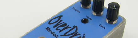
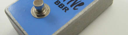
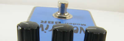
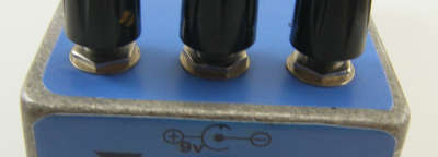
This is a replica of the Marshall™ BlueBreaker Distortion referred to as MBB in these documents. (Trademarks mentioned here do not belong to General Guitar Gadgets) Use the project documents provided, starting with the General Build Instructions. Follow the layout diagrams to add components to the PCB and the wiring diagrams to hook it all up. There are photos in this document to give some ideas of the overall layout and wiring. Note that the original stompboxes had doubled coupling capacitors and resistors between the opamp stages (with non-true bypass between them). These have been combined and true bypass added. Comments and questions are welcome and can be sent to [email protected] Here is a chart of voltages taken at the IC pins. This information can be used to help you find and fix problems if your MBB doesn't work when you test it. These are approximate voltages, if yours are within one volt variance, you are probably okay, however, pin 4 should be zero volts and pin 8 should be same voltage as the 9v+. Note that there is a voltage drop in circuit "operating voltage" due to the protection diode (D5). D5 is a small Blue diode in the Kits.

Component
Location
9 volt power supply IC1
Voltage
8.8v
Pin 1
4.3v
Pin 2
4.3v
Pin 3
3.9v
Pin 4
0v
Pin 5
4.3v
Pin 6
4.3v
Pin 7
4.3v
Pin 8
8.8v
Here's a look inside (with modification for dual clipping switch):




Questions
Frequently asked questions
How is this different from a Tube Screamer™?
Lower gain and no mid hump: the Bluesbreaker™ is an amp-like edge-of-breakup overdrive that keeps your guitar's own tone. Stack it into a Tube Screamer™ for a lead boost.
What does the King of Tone add-on do?
Extra clipping diodes after the op-amp, a presence control and clipping-select switches, turning the MBB into a two-mode drive like the Analog Man pedal. It's a small add-on kit for this board.
Original or true bypass?
The kit is true bypass with an LED. The original's buffered wiring is in the schematics if you want it exactly as 1989.
Can I get more gain?
Raise R10 from 220k to 330k; for more bass in the tone control, change C8 and C9 to 0.022 µF. Both are in the mod guide.
Make it your own
Modification Instructions
Version 2019July17 · Copyright 2018 JD Sleep · Permission refused for posting/serving this file from any site other than www.generalguitargadgets.com · Trademarks are property of their owners
King of Tone-Type Mods
These modifications are covered with a set of diagrams (Schematic and Layout Diagrams) on the BluesBreaker™ Project Page, so they are shown separately within those diagrams. Basically they are an added set of clipping diodes after the IC stages and a series resistor into the Gain control. Both sets of clippers are selectable by switches. There is also a “Presence” control added to the tone control network to tone down the treble that may take some of the harshness off going into some amplifiers
Morning Glory-Type Mods
These modifications are covered with a set of diagrams (Schematic and Layout Diagrams) on the BluesBreaker™ Project Page, so they are shown separately within those diagrams. Basically the modifications are: a small cap in the IC feedback loop to mellow the tone a bit and the circuit is followed by a FET booster to bring back some luster to the sound after the Tone Control (You can see a similar thing in the Rat™ and Red Fuzz Distortion pedals).
Clean Boost or Clipper Switching
Modifications The PCB is equipped with pads for switching in and out the feedback clipping and the Post-IC clipping. To get a clean boost, just switch off the clipping
Combinations
There are a lot of variations you can build into this with the various clipper switches. A DPDT on-off-on switch can be used to select either set of clippers or none for a cleaner boost sound or you can have separate SPST switches for each. They can be internal DIP switches (on a perf board) or mounted on the top of the pedal.
More Gain
Change R10 from a 220K to a 330K to get a slightly more gain .
More Bass in the Tone
Change C8 & C9 from the stock 0.01uf capacitors to a 0.022uf capacitors. It will make the tone control work better for some guitar/amp combinations & has a little more bottom end Want to contribute? If you are happy to share your modification information with other builders, contact us at [email protected]. If the modifications pass our review we will add it to this file for all to enjoy!
More about this project
Notes, sounds and related links
MBB Modified Version Files
MBB Older Blue PCB Layout File (no longer for Sale)

Ready to build? We have the kit.
Buy a MBB Complete Kit. Includes all the parts and materials you need to build one, all for about the price you would pay for a PCB and parts.
Would you like a Ready to Solder Circuit Board for this project?
Note: If you buy the kit, the Ready-to-Solder Printed Circuit Board (RTS PCB) is included in the kit. You do not need to purchase this Ready to Solder Circuit Printed Board if you buy the kit.
