
Project · Compression
MXR™ Dynacomp™
In the 1970's, the MXR™ Dynacomp™ compressor was another ground breaking innovation from the original MXR™ company. Soon after its release, it became standard equipment for Fender™ Telecaster™ players and the Nashville sound was forever changed (for the better, obviously!). This project is based on the original Dynacomp™ from the "real" MXR™ Innovations™ company as built in the '70's, not the ones currently built by Dunlop Manufacturing, Inc. We added true bypass and an LED indicator, but that will not alter the tone of this great compressor. The Ross™ Compressor was copied from this compressor and is treasured by many players as being "the one" compressor. At General Guitar Gadgets we believe that the Dynacomp™ is an excellent compressor and rates as high as the Ross™ as a great compressor. Note that this project uses the same PCB and Kit as the Ross™ Compressor.
Project files
Everything you need to build it
Dynacomp™ Compressor Ready-For-Transfer Printed Circuit Board Layout For use only if you are a complete DIY person who wants to etch and drill your own PCB. Otherwise, we recommend you ignore this PCB mask and buy the Ready to Solder Printed Circuit Board.
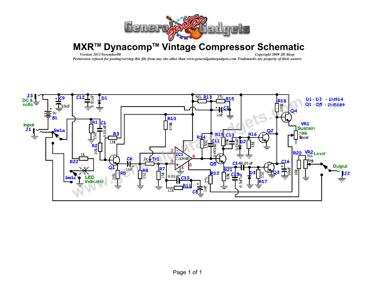
Parts layout
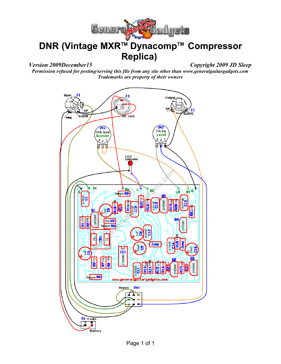
Parts Layout / Wiring Diagram
What you will need
Bill of Materials
Version 2012January30 · Copyright 2009 JD Sleep · Permission refused for posting/serving this file from any site other than www.generalguitargadgets.com · Trademarks are property of their owners
Resistors
| Resistor ID | Value | 3-band Marking | 4-band Marking |
|---|---|---|---|
| R1 | 1M5 (1.5M) | brown-green-green | brown-green-black-yellow |
| R2 | 10k | brown-black-orange | brown-black-black-red |
| R3 | 1M | brown-black-green | brown-black-black-yellow |
| R4 | 0 ohm or jumper wire | black | black |
| R5 | 10k | brown-black-orange | brown-black-black-red |
| R6 | 0 ohm or jumper wire | black | black |
| R7 | 1M | brown-black-green | brown-black-black-yellow |
| R8 | 1M | brown-black-green | brown-black-black-yellow |
| R9 | 0 ohm or jumper wire | black | black |
| R10 | 470k | yellow-violet-yellow | yellow-violet-black-orange |
| R11 | 15k | brown-green-orange | brown-green-black-red |
| R12 | 27k | red-violet-orange | red-violet-black-red |
| R13 | 56k | green-blue-orange | green-blue-black-red |
| R14 | 150k | brown-green-yellow | brown-green-black-orange |
| R15 | 27k | red-violet-orange | red-violet-black-red |
| R16 | 1M | brown-black-green | brown-black-black-yellow |
| R17 | 1M | brown-black-green | brown-black-black-yellow |
| R18 | 150k | brown-green-yellow | brown-green-black-orange |
| R19 | 10k | brown-black-orange | brown-black-black-red |
| R20 | 10k | brown-black-orange | brown-black-black-red |
| R21 | 10k | brown-black-orange | brown-black-black-red |
| R22 | 1k | brown-black-red | brown-black-black-brown |
Capacitors
| Capacitor ID | Value | Type | Possible Marking |
|---|---|---|---|
| C1 | 0.01µF | Film | 103 |
| C2 | none | ||
| C3 | 1µF | Aluminum Electrolytic | 1uF |
| C4 | none | ||
| C5 | none | ||
| C6 | 1µF | Aluminum Electrolytic | 1uF |
| C7 | none | ||
| C8 | 1µF | Aluminum Electrolytic | 1uF |
| C9 | 10µF | Aluminum Electrolytic | 10uF |
| C10 | 0.01µF | Film | 103 |
| C11 | 0.001µF | Film | 102 or 1n |
| C12 | 0.01µF | Film | 103 |
| C13 | 0.01µF | Film | 103 |
| C14 | 0.01µF | Film | 103 |
| C15 | 0.047µF | Film | 473 |
| C16 | 10µF | Aluminum Electrolytic | 10uF |
Potentiometers
| Part ID | Value | Type |
|---|---|---|
| VR1 - Sustain Control | 500k | Linear Taper |
| VR2 – Level (Volume) Control | 50k | Log (or Audio) Taper |
| TR1 – Trimmer | 2k | Can be replaced by two 1k resistors as shown in the layout |
Other
| Part ID | Part Name |
|---|---|
| IC1 | CA3080 |
| D1, D2, D3 | 1N914 |
| D4 | LED |
| Q1, Q2, Q3, Q4, Q5 | 2N5089 |
| J1 | Stereo quarter-inch jack |
| J2 | Mono quarter-inch jack |
| J3 | DC Jack |
| B1 | 9 volt battery |
| Sw1 | Heavy Duty 3PDT foot switch 9v battery snap, Printed Circuit Board, 24 gauge stranded wire, Enclosure, Knobs, Rubber Feet, PCB Standoffs |
How to build it
Instructions
Version 2014December30 · Copyright 2013 JD Sleep · Permission refused for posting/serving this file from any site other than www.generalguitargadgets.com · Trademarks are property of their owners
This is a replica of the MXRTM DynacompTM Compressor referred to as DNR in these documents. This compressor is one of the all time “classic” compressors and has a great sound. Use the project documents provided, starting with the General Build Instructions. The original unit used the now obsolete 2SC1849 transistors. The current production 2N5089 transistors are quieter and sound excellent in this circuit. If you want to source some 2SC1849 transistors, you will need to twist the pins around to fit in the CBE format that this PCB uses. The sound difference between tantalum capacitors and aluminum electrolytic capacitors is very subtle, if even at all detectable to the ear. You would most likely not hear any difference. It's also debatable which type of capacitor would sound better (if you could hear the difference). We have found that either Tantalum or Aluminum Electrolytic both sound good. The original units had ceramic capacitors that we have upgraded to film. Outside of distortion circuits, there is usually no debate that film will sound better than ceramic (if you can hear the difference).
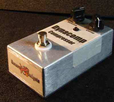
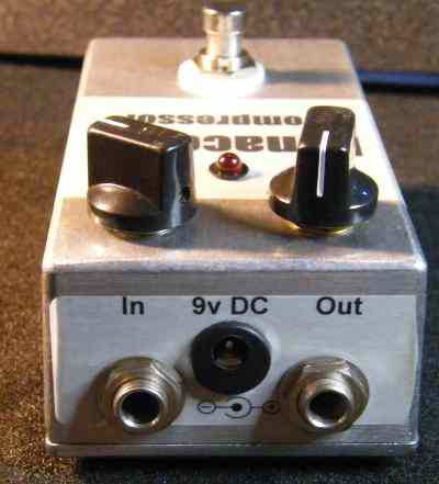
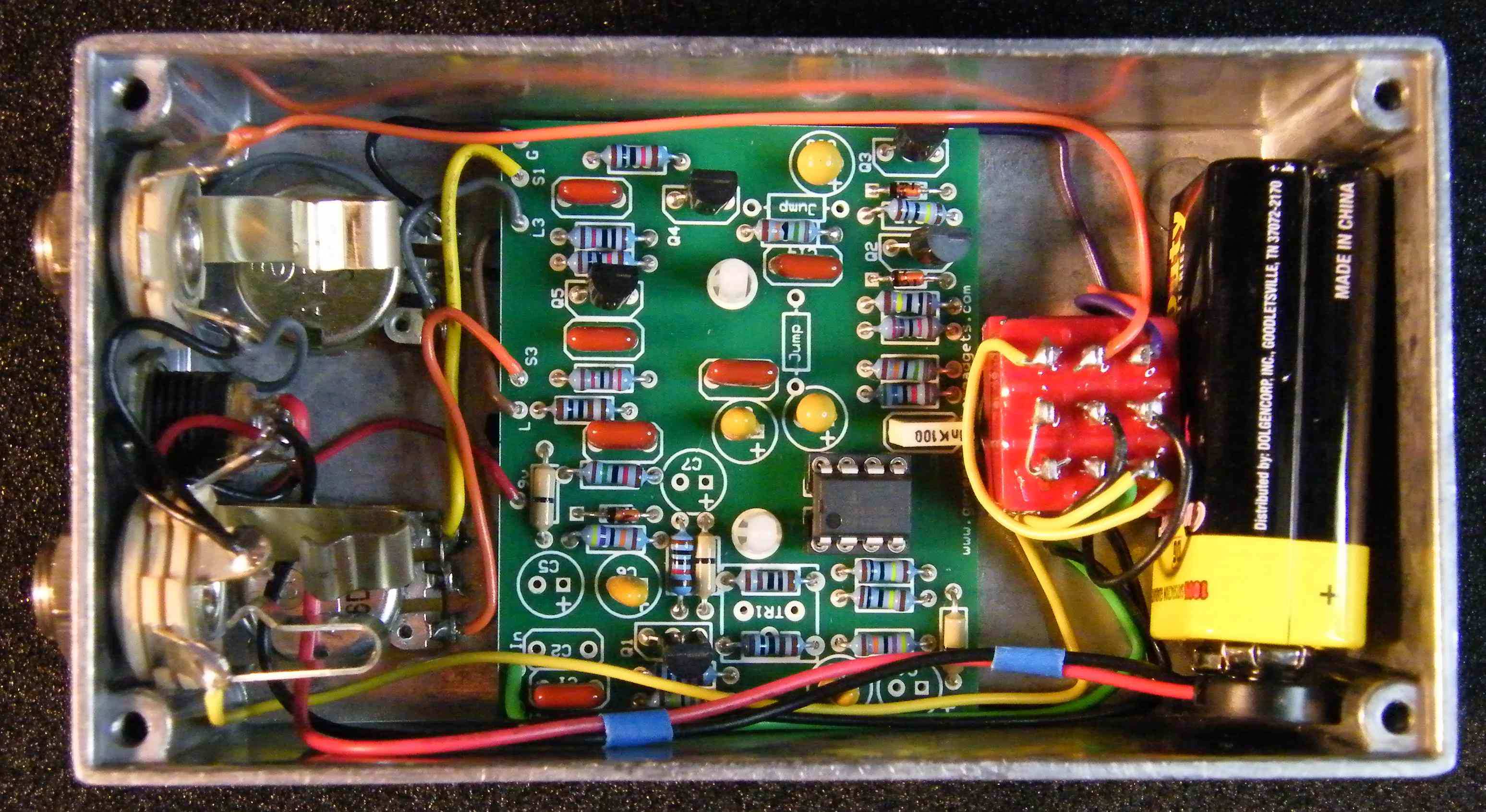
Here's an inside view of the unit we built to give you some general ideas if needed.
Comments and questions are welcome and can be sent to [email protected] Here is a chart of voltages taken at the transistor and IC pins. This information can be used to help find and fix problems if your OSQ doesn't work when you test it.
Component
Location
9 volt power supply Q1
Voltage
9.3v
Collector
7.5v
Base
2.4v
Emitter
2.0v
Q2
Q3
Q4
Q5
IC1
Collector
9.3v
Base
.05v
Emitter
0v
Collector
9.3v
Base
0.5v
Emitter
0v
Collector
9.3v
Base
8.9v
Emitter
8.6v
Collector
7v
Base
3.1v
Emitter
2.6v
Pin 1
0v
Pin 2
4.4v
Pin 3
4.4v
Pin 4
0v
Pin 5
0.7v
Pin 6
3.0v
Pin 7
9.3v
Pin 8
0.0v
More about this project
Notes, sounds and related links


Ready to build? We have the kit.
Buy a DynaComp Compressor Complete Kit. Includes all the parts and materials you need to build one, including the PCB, all for about the price you would pay for a PCB and parts.
Would you like a Ready to Solder Circuit Board for this project?