Parallelyzer
The Concept
The Parallelyzer (pronounced Paralyzer with a little stutter in the middle) is a concept I’ve been dreaming of for a while. Thanks to Mark Hammer for bringing this up on Aron’s Stompbox Forum. He had some great ideas in addition to what I was dreaming up, and his posting encouraged me to write this up. Even if you don’t have a need for this box as a unit, you might find some ideas here that you can use somewhere in your effects processing chain.
The idea is to make a single box that has two or more effects loops that you can switch in and out or even run in parallel (thus the name – Parallelyzer). This project is open to be customized to your own needs. The options are mostly determined by the switching scheme, number of loops and the output options you choose.
There has been a lot of discussion on the forums about loops and switching and effects order switching. There is an article or two on the GEO site with some good switching schemes. This project is meant to be a simple, easy to understand, easy to implement little system that could be something useful to many of us. The GEO switcher is great, but this project meets most of my needs, is easier to build and has some additional built-in features. Be forewarned that there is nothing new or original in this project. It’s just putting together several ideas and schematics that are already floating around on the net. Everything is based on circuits designed by R.G. Keen, Craig Anderton and Forrest M. Mims III.
Lets take a look at the basic block diagram of the Parallelyzer:
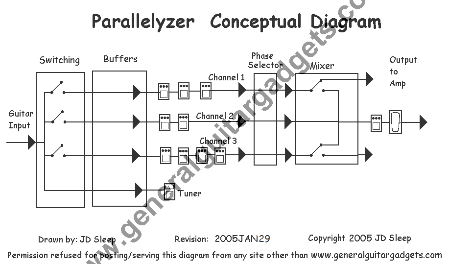
The Parallelyzer consists of four sections;
- Switching
- Buffering
- Effects Loops
- Phase Selection
- Mixing
The guitar cable is plugged into the input of the Parallelyzer. The signal then goes into a splitter and a switching section which determines which path(s), or channel(s), the guitar signal will go through. This section is greatly simplified in the Conceptual Diagram. We’ll get into the details of switching options a little further down the page.
Out of the switching section, the signal is then buffered to give a good clean low impedance signal in each channel. The buffers could also be built to give a little boost at the input of your effects loops as well.
After the buffers, the signal paths (channels) leave the Parallelyzer box and go to “loops” of stompbox effects, or series of stompboxes, that are plugged into the various channels and then plugged back into the Parallelyzer.
The next section, the Phase Section, allows you to control the phase of the signal wave of each channel. Phase selection is simply a toggle switch on each channel that reverses the phase of the signal wave. This allows you to get all the channels in phase, in case some of your effects throw you out of phase with other channels.
From here the signals go to the mixer section, where they can then be mixed back into one signal, or output to separate amp channels or separate amps. The two switches in the mixer section show how you can implement switches to choose to mix into one output signal or send the signal straight out to the amps, or combinations with some channels mixed and some bypassing the mixer. In the diagram, the switches are set to mix channels 2 and 3. Channel 1 is output to a separate amp channel without being mixed with the other channel signals.
The diagram also demonstrates that you can add more effects on after the Parallelyzer output, like an echo effect and a volume pedal. Of course you could also string some effects in front of the Parallelyzer input, and that is not shown on the diagram. Don’t forget you can also add a true-bypass switch around the Parallelyzer to bypass this entire unit.
Switching
There are many switching options available. Here are a few common ones and you can probably think of even more options:
- No switching at all. The Parallelyzer would run all channels in parallel at all times.
- On/Off switches for each channel. This gives you a lot of options, but makes switching from loop to loop a two switch operation.
- Loop selection switches that switch between two loops.
- Combinations of the items listed above.
- Status indicator LEDs to show which loops are active.
Let’s look at some diagrams of some switching options you can use. You may want to have some combination of switching options. Here are some diagrams with some switching schemes:
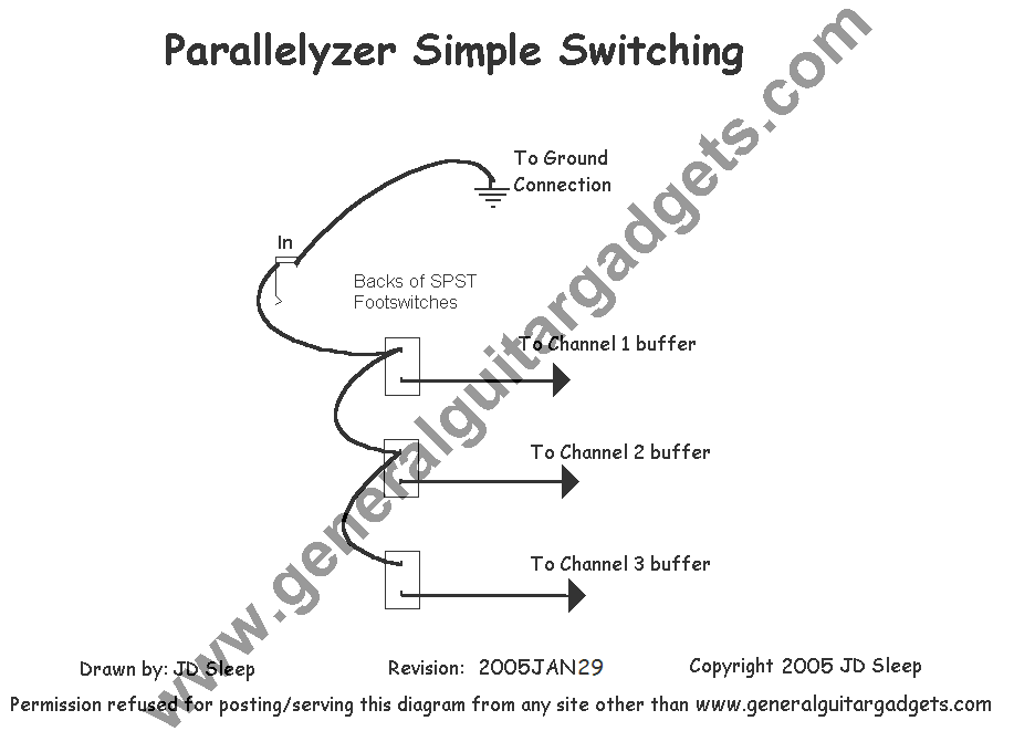
Here is the simplest option. It uses 3 – SPST footswitches. These footswitches are considerably less expensive than the DPDT footswitches so if you are on a budget and you can go without channel indicator LEDs, this is the way to go.
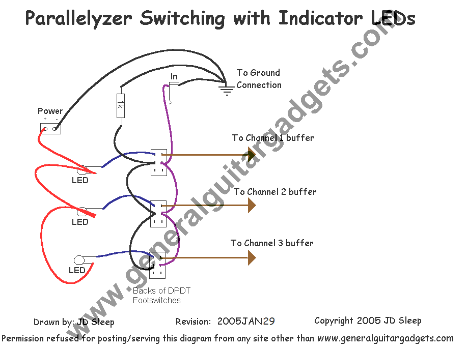
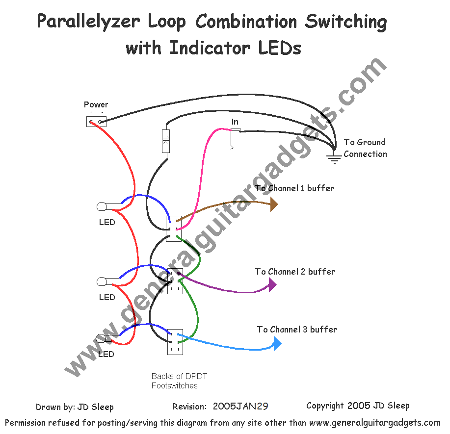
Here is one scheme for ON/OFF switching on each channel with indicator LEDs included. The LED will be lit when the channel is active. Here you will need three DPDT switches.
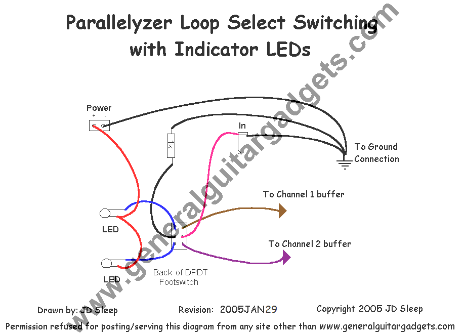
You can simplify your Paralellyzer by just having two loops and have switching between the two loops. This scheme shows two loop switching with LED indicators for the active channel.
Here’s the switching scheme that I have chosen. It has some combination switching that allows one-switch operation for flipping back and forth between two loops. It also allows for some simple parallel processing, which is optional based on the position of the ON/OFF switches for channels 2 and 3. It also has LED indicators for the active channel(s). This might give you some ideas of using switching combinations. Notice that if you switch over to channel 2 & 3 (the top switch) and then turn off channels 2 & 3 you can cut your signal completely off, good for silent tuning. There are thousands of switching scheme possibilities for just a simple three-channel Parallelyzer!
Buffers
The electronics theory behind buffers and impedance will not be discussed here in detail. Let me just say that buffers are “a good idea” here, where the signal is split. You might be able to get by without the buffer section, but in general your effects loops will sound better with the buffers in front. Let’s look at a typical opamp buffer as designed by Craig Anderton, and featured in the October 1976 issue of Guitar Player Magazine:
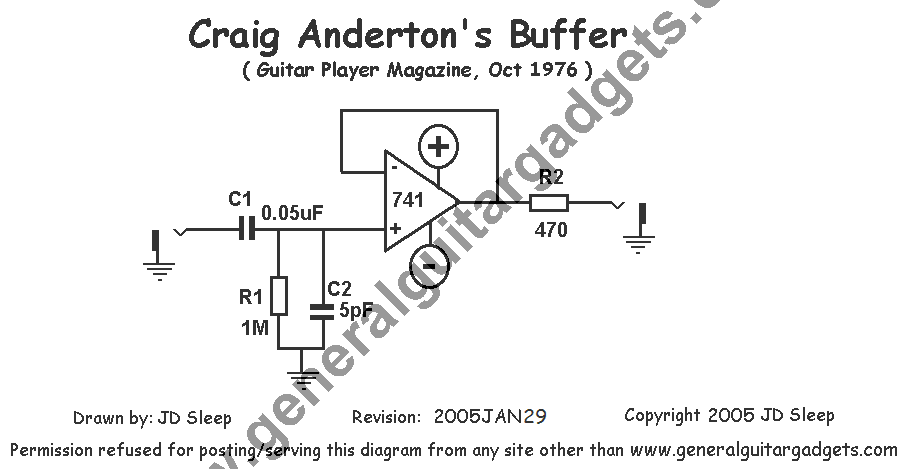
Anderton’s Guitar Player article suggests using a quad opamp IC to make a four-way buffer and in his book Electronic Projects For Musicians a “Spluffer” project is a two-way splitter with buffered outputs. He did not suggest using a single 9v battery power source, but we will do that for our purposes. This is the basic buffer design that we will be using for this project.
Phase Selector
If you run two or more channels in parallel at any time, you should have some control over the phase of each channel. Given the plethora of effects available for guitar and knowing several personally that reverse the phase of your guitar signal, there’s a pretty good chance your channels aren’t going to be in phase with each other. This will weaken your signal in the end as the two signals come together and partially cancel each other out. There are a couple of options for a phase reversal switch. Here is a A link to a Phase Reversing Article from GEO. This is a great little circuit. Craig Anderton’s Phase Switcher Project (project 11) from his book DIY Projects For Guitarists is good as well, but of course, Anderton’s requires bipolar power.
Mixer
RG Keen’s Simple Mixer circuit has been on the net for years. This is the circuit that I will be using for the mixer section of the Parallelyzer. I’ve decided not to include any EQ in this section, let’s keep it simple. Another feature to consider in the mixer (output) section is some transformer isolation of the outputs if you are planning on output going to two or more amps.
Putting It All Together
There are a multitude of variations that this project could take. I decided to keep it modular and make three separate circuit boards (buffers, phase selectors and mixer). This gives good flexibility for reworking the box later on in life when my needs will probably change. I would love to build this right into my pedal board (along with the GEO spyder). I think that would be the ultimate, and I may well build a new pedal board one of these days. I’ve already shown the switching scheme that I have chosen and the Basic Block Diagram shows some of my other choices; four channels, one devoted to a tuner input, and three loops. The following project files are laid out for this particular variation. Of course you may decide on more or less channels and other switching features, adding EQ circuits, etc. Make alterations to the project to suit your own needs.
