
Project · Boosters & Volume
Fryer/Brian May Treble Booster Replica
Here is a very popular treble Booster. This project is built on the Germanium Booster (GEB) board, though it uses a silicon transistor. It is a very nice sounding, reliable circuit.
The story
About the circuit
Brian May's sound is a Vox™ AC30 driven hard by a treble booster, with the guitar's volume control doing the rest. He used a Dallas Rangemaster™ in Queen's early days and later boosters built for him, and the Australian luthier Greg Fryer, who restored May's Red Special in 1998, went on to make the boosters May has used since. A treble booster is a single-transistor gain stage with a small input capacitor that rolls off bass, so what hits the amp is a loud, bright signal that pushes the preamp into a singing, vocal overdrive rather than mud. This project follows the Fryer-style Brian May booster circuit.
This project at GGG
Our Germanium Booster board was designed so that one PCB could build the Rangemaster™ and its relatives, and the Brian May booster was a natural addition even though it uses a silicon transistor; it has been here for well over a decade. It is a reliable, low-parts-count build, and the Tone Booster Notes and Modifications sheet that goes with it covers the tweaks we have tried over the years. A favourite with AC30 and Marshall™ players who want the amp to do the distorting.
Project files
Everything you need to build it
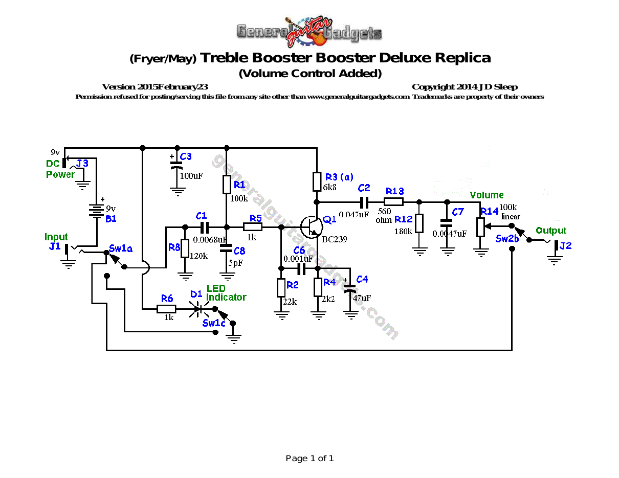
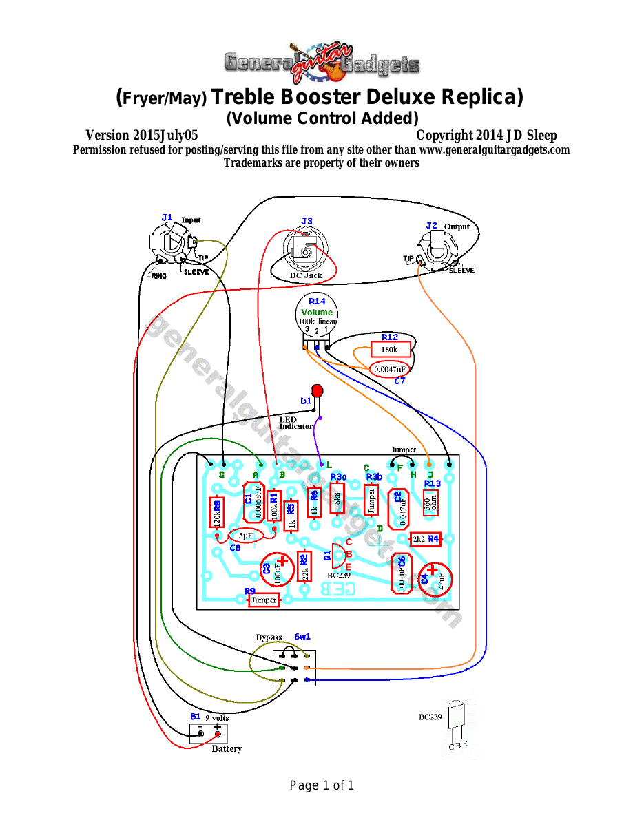
What you will need
Bill of Materials
Version 2021JAugust31 · Copyright 2009, 2021 JD Sleep · Permission refused for posting/serving this file from any site other than www.generalguitargadgets.com · Trademarks are property of their owners
Resistors
| Resistor ID | Value | 3-band Marking | 4-band Marking |
|---|---|---|---|
| R1 | 100k | brown-black-yellow | brown-black-black-orange |
| R2 | 22k | red-red-orange | red-red-black-red |
| R3a | 6k8 (6.8k) | blue-gray-red | blue-gray-black-brown |
| R3b | 0 ohm or jumper wire | black | black |
| R4 | 2k2 (2.2k) | red-red-red | red-red-black-brown |
| R5 | 1k | brown-black-red | brown-black-black-brown |
| R6 | 1k | brown-black-red | brown-black-black-brown |
| R7 | Blank | ||
| R8 | 120k | brown-red-yellow | brown-red-black-orange |
| R9 | 0 ohm or jumper wire | black | black |
| R10 | Blank | ||
| R12 | 180k (off board) | brown-gray-yellow | brown-gray-black-orange |
| R13 | 560 ohm (In the space for C5 on the PCB) | green-blue-brown | green-blue-black-black |
| R14 (Volume Control) | 100k Linear Potentiometer |
Capacitors
| Capacitor ID | Value | Type | Possible Marking |
|---|---|---|---|
| C1 | 0.0068µF | Film or ceramic | 682 or 6n8 |
| C2 | 0.047µF | Film or ceramic | 473 |
| C3 | 100µF | Aluminum Electrolytic | 100µF |
| C4 | 47µF | Aluminum Electrolytic | 47µF |
| C5 | None - R13 is in this space on the PCB | ||
| C6 | 0.001µF | Film or ceramic | 102 or 1n0 |
| C7 | 0.0047µF (off board) | Film or ceramic | 472 |
| C8 | 5pF | Ceramic | 5 |
Potentiometers
| Part ID | Value | Type |
|---|---|---|
| R14 - Volume Control | 100k | Linear Taper |
Other
| Part ID | Part Name |
|---|---|
| D1 | 1N914 (Optional) |
| D2 | LED |
| Q1 | BC239 or other similar NPN transistor |
| J1 | Stereo quarter-inch jack |
| J2 | Mono quarter-inch jack |
| J3 | DC Jack |
| B1 | 9 volt battery (not included in the Kit) |
| Sw1 | Heavy Duty 3PDT foot switch 9v battery snap, Printed Circuit Board, 24 gauge stranded wire, Enclosure, Knobs |
How to build it
Instructions
Tone Booster Notes and Modifications
Version 2015January21 · Copyright 2014 JD Sleep · Permission refused for posting/serving this file from any site other than www.generalguitargadgets.com · Trademarks are property of their owners
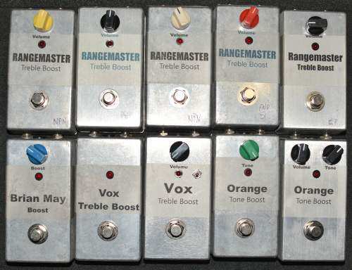
- There are several Tone Boosters or Treble Boosters with a similar circuit and can be
- built on the same GEB Booster PCB that we offer. As you can see from the photo
- above, we have built several variations of Tone Boosters. We offer kits or the PCB to
- build modern replicas for these Treble/Tone Boosters:
Apollo Tone Booster
Fryer/May Treble Booster Orange Tone Booster Dallas Arbiter™ Rangemaster™ Vox™ Treble Booster
From these basic brands of Treble/Tone Boosters there are lots of variations and modifications that can be added. In this document we will explore some of the similarities & differences, modifications & quirks and other interesting facts & features of these wonderful Tone Boosters.
Transistors
Some of these boosters have a Germanium transistor and some have a Silicon transistor. Throughout this document we will use GE to mean Germanium and SI to mean silicon. We like both the GE and SI transistors in the boosters. The type of transistor is specified in documents associated with the brand of booster you are building. We have built Rangemaster™ with PNP and NPN GE transistors and also tried it with SI transistors. We like them all. NPN versions work with your other pedals on a shared power supply. PNP versions can be on shared power supply only with other PNP circuits, unless you use the Charge Pump wrapper in the circuit as described in that document (available on the Tone Booster project pages). Volume Control With the exception of the Rangemaster™, none of these boosters had a volume control. In today's market of guitar effects, having a booster with no volume control is nothing less than absurd. It was acceptable in the 1960's or early '70's when they first came on the scene and some of the Vox™ boosters were on-board on Vox™ guitars where the volume knob was handy, but we believe that most players would agree that we need a volume control on a booster stompbox. Thankfully, this is a very easy modification and does not effect the overall tone of the booster. Just add a pot at the end of the circuit in typical volume control fashion. We settled on a 100k linear pot, but any value or taper pot will work. Our replicas include, and we recommend adding a volume control. Bypass Switch Click While working with DIY replicas of all these different boosters we noticed one thing that they all had in common: they are all very susceptible to bypass switch pop. We added a pull down resistor on the input and output of all the versions and this stopped the pop and also doesn't effect the tone as far as we could tell. That is to say that we didn't notice any tone differences in the testing we did. It should be noted that if you use a volume control modification, then you don't need the pull down resistor on the output (R11) and due to the pot on input of the Orange & Apollo Boosters, they don't need a pull down resistor on the input (R8). Input Capacitor We have found that there is a great amount of interaction between the input cap (C1) and the transistor used as Q1. The interaction effects treble, distortion and overall volume output. For example, generally speaking, with lower hFE transistors, a small value input capacitor will give some extreme treble and not much volume boost. With
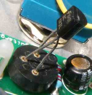
higher hFE transistors the same input cap (C1) doesn't give much treble boost but may give a great “boxy” mid-range sounding booster with lots of volume. With a larger input cap, you get into some very nice distortion sounds. You can tune your booster to have many different sounds just by variations in C1 and Q1. After you decide on a transistor for Q1, it makes a great modification to have a switchable input cap, which is what we have done on some of the units we built. The Tone Boosters We found that the Tone Control on the Apollo and Orange Boosters is very useful for tuning in the amount of treble or mid boost, but the bass boost on the lower half of the pot rotation was not useful for us, at least not for our simple sound tests. Also it should be noted that some volume is lost on the lower half of rotation of the Tone Control. Transistor Selection In our replicas, we tried to stick with similar or the same transistor types as used in the originals. We believe the silicon models (Fryer/May and Vox™) sound as good as or better (in some ways) than the germanium models (Rangemaster™, Orange and Apollo). They are all basically the same circuit with variations. The resistor and capacitor values are selected to work best with the type of transistor used. With capacitor modifications, any of them can be built to offer a distortion sound or can be built to be fairly clean boosters. The GE transistors have a bit more gritty sound, the SI transistors offer a more stable, reliable sound. Power If you use 9v battery power exclusively, then power is not an issue with the PNP circuit pedals. Any of the GE versions can be built with NPN GE transistors or PNP versions with a charge pump so that they can run on shared power with all your other pedals. We have a wiring diagram that shows the Rangemaster™ version with the charge pump “wrapper”. The power and ground wiring for the other PNP version would be wired the same way. Transistor Placement and Sockets Transistor sockets are provided with the kits. Some people like sockets, some people don't so use your own discretion when building your kit. The layout uses a CBE transistor pin pattern, some SI transistors have a ECB pattern and the pins need to be placed accordingly. See the photos below.
Modifications
1. Add a volume control as mentioned above. This modification can be seen on the wiring diagrams of the Fryer/May Booster and the Vox™ Booster. And it can be applied to any of the boosters, although the Rangemaster™ already has a volume control of a different kind. 2. Add a switchable input capacitor. This modification can be seen on a modified layout/wiring diagram on the Vox™ Booster Project page. This is a power-packed modification and can really give you a variety of sounds. 3. Any of the originally PNP circuits can be replaced with NPN circuits if you find a good NPN transistor replacement. There are layout/wiring diagrams for the Rangemaster™ and Orange Booster project pages. The others were originally NPN circuits. 4. Any of the PNP circuits can be powered by a charge pump circuit so that they can share power with most other negative-ground-circuit stompboxes. There are wiring diagrams for this on the project pages for each booster and there is a little kit available if you want to include it in your stompbox.
Brian May Treble Booster Instructions
Version 2015July05 · Copyright 2014 JD Sleep · Permission refused for posting/serving this file from any site other than www.generalguitargadgets.com · Trademarks are property of their owners
- This is a replica of the Gregg Fryer/Brian MayTM Treble Booster. Follow the
- General Instructions and the Layout/Wiring Diagram.
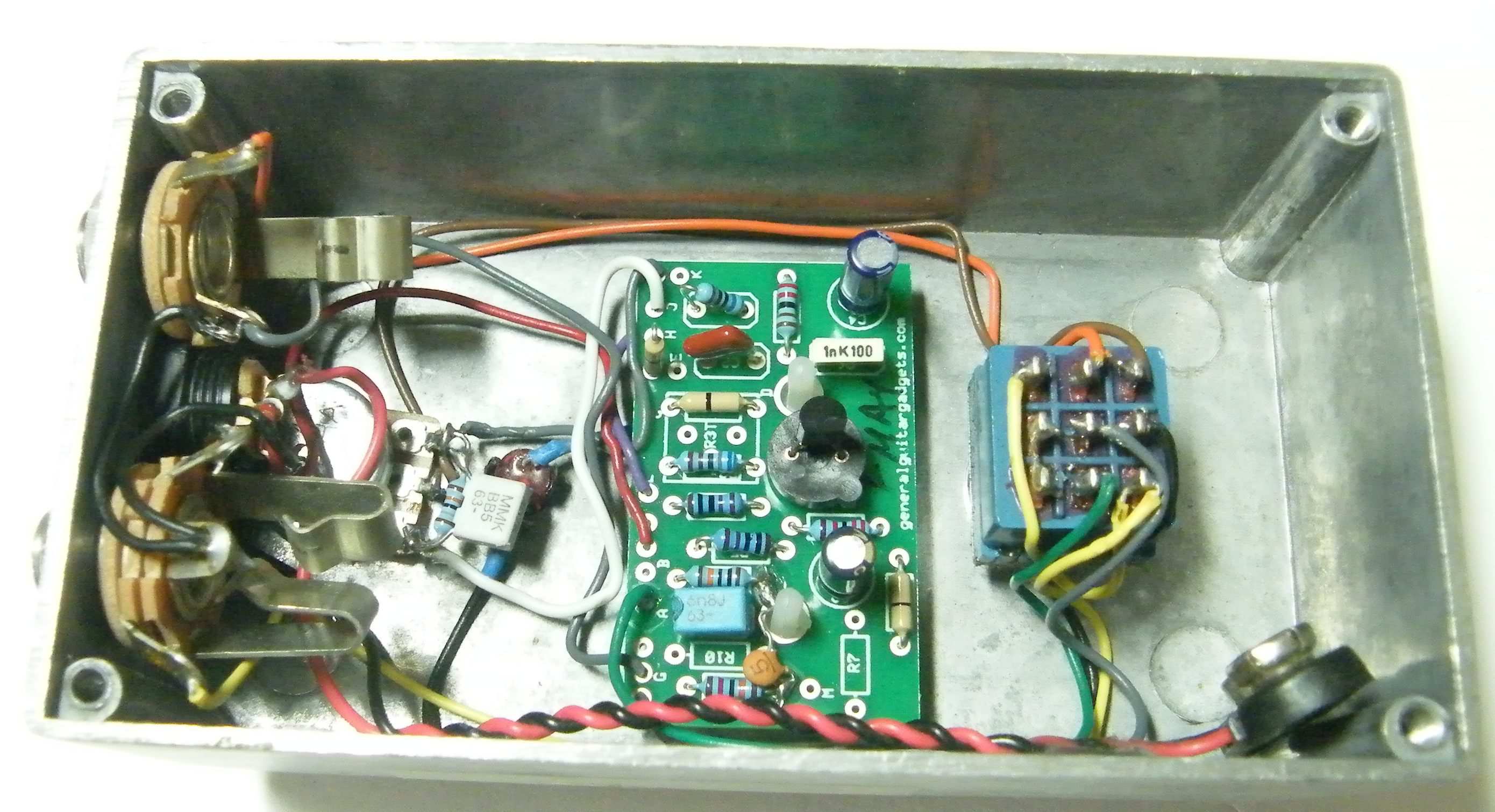
The original unit did not have a Volume control. We added a volume control because it just seems to make sense. When the volume is on full, the circuit is the same as the original that doesn't have the volume control. There is some off-board wiring for R12 and C7. These components need to be solder tacked between lugs 3 and 1 of the volume control. Probably the easiest way to do this is to solder the resistor between the pot lugs and then solder tack the capacitor parallel onto the resistor (see photo below). C8 will need to be solder tacked between the ground point on the leg of R8 and the inside end of R1 (see the wiring diagram and the photo below for details.) The Kit comes with a BC239A transistor as the originals.
Here is a photo of the inside of the Treble booster.
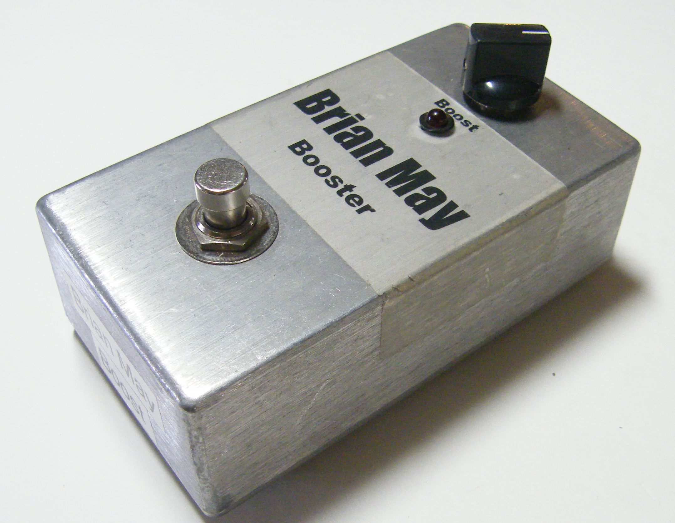
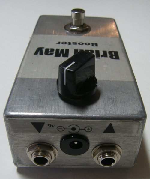
Here is a chart of voltages taken at the BC239 transistor pins. Use these voltages as a guideline. You may not get the exact readings listed, but should be somewhere in the area.
Component
Location
9 volt power supply Q1 (BC239A)
Voltage
9.2v
Collector
6.3v
Base
1.7v
Emitter
1.0v
Ready to build? We have the kit.
Buy a Brian May Booster Replica Complete Kit. Includes all the parts and materials you need to build one, all for about the price you would pay for a PCB and parts. 
Would you like a Ready to Solder Circuit Board for this project?
