
Project · Bass
Ibanez™ BP10™ Compressor Relica
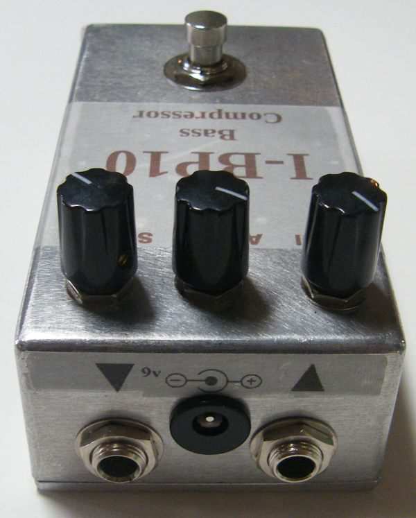
This is the awesome Ibanez™ BP10™ Compressor replica project. An excellent sounding bass compressor. This project uses the same PCB as the Ibanez™ CP10™ Compressor, they are nearly the same circuit, with only two capacitor values difference. A very nice (and under-rated) compressor. The Ibanez™ "10" series has always been plagued by a bad reputation because the plastic jacks and pots with plastic shafts that make repairs difficult or impossible. Of course those problems are not an issue with this replica! Build yourself a reliable and great sounding compressor. All trademarks mentioned here are property of their owners and NOT General Guitar Gadgets
The story
About the circuit
The BP10™ was the bass compressor in Ibanez™'s 1980s "10 series", the twin of the CP10™ guitar compressor with two capacitor values changed to suit bass. It evens out the attack of a bass, fingerstyle or slap, so every note sits at the same level in the mix, and it does it smoothly enough that you hardly hear it working. The series' plastic jacks and plastic-shafted pots have kept it under-rated and cheap on the used market.
This project at GGG
Our BP10™ replica uses metal jacks and proper pots, so those reliability problems don't apply. It shares one board with our CP10™, so the same kit builds either the bass or the guitar version. Like the CP10™, it is a little more involved than our other compressors, with nearly all the resistors standing on end, and the instructions show how they should sit.
Project files
Everything you need to build it
Ibanez™ BP10™ Bass Compressor Ready-For-Transfer Printed Circuit Board Layout For use only if you are a complete DIY person who wants to etch and drill your own PCB. Otherwise, we recommend you ignore this PCB mask and buy the Ready to Solder Printed Circuit Board.
Schematic
Schematic
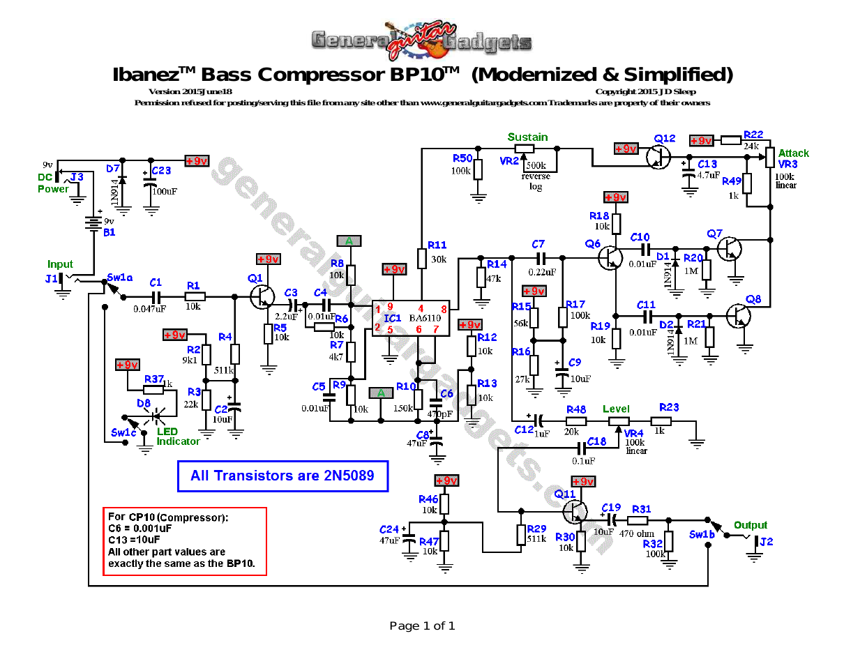
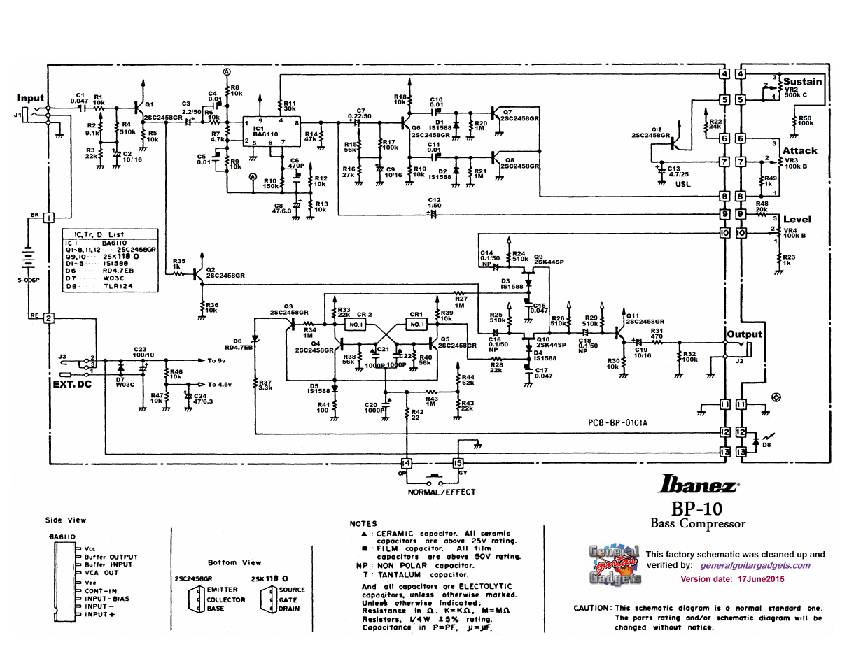
Parts layout
Parts Layout / Wiring Diagram
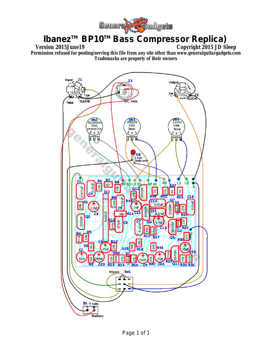
What you will need
Bill of Materials
Version 2015July02 · Copyright 2015 JD Sleep · Permission refused for posting/serving this file from any site other than www.generalguitargadgets.com · Trademarks are property of their owners
Resistors
| Resistor ID | Value | 3-band Marking | 4-band Marking |
|---|---|---|---|
| R1 | 10k | brown-black-orange | brown-black-black-red |
| R2 | 9k1 (9.1k) | white-brown-red | white-brown-black-brown |
| R3 | 22k | red-red-orange | red-red-black-red |
| R4 | 510k (511k Metal Film) | green-brown-yellow | green-brown-brown-orange |
| R5 | 10k | brown-black-orange | brown-black-black-red |
| R6 | 10k | brown-black-orange | brown-black-black-red |
| R7 | 4k7 (4.7k) | yellow-violet-red | yellow-violet-black-brown |
| R8 | 10k | brown-black-orange | brown-black-black-red |
| R9 | 10k | brown-black-orange | brown-black-black-red |
| R10 | 150k | brown-green-yellow | brown-green-black-orange |
| R11 | 30k | orange-black-orange | orange-black-black-red |
| R12 | 10k | brown-black-orange | brown-black-black-red |
| R13 | 10k | brown-black-orange | brown-black-black-red |
| R14 | 47k | yellow-violet-orange | yellow-violet-black-red |
| R15 | 56k | green-blue-orange | green-blue-black-red |
| R16 | 27k | red-violet-orange | red-violet-black-red |
| R17 | 100k | brown-black-yellow | brown-black-black-orange |
| R18 | 10k | brown-black-orange | brown-black-black-red |
| R19 | 10k | brown-black-orange | brown-black-black-red |
| R20 | 1M | brown-black-green | brown-black-black-yellow |
| R21 | 1M | brown-black-green | brown-black-black-yellow |
| R22 | 24k | red-yellow-orange | red-yellow-black-red |
| R23 | 1k | brown-black-red | brown-black-black-brown |
| R29 | 510k (511k Metal Film) | green-brown-yellow | green-brown-brown-orange |
| R30 | 10k | brown-black-orange | brown-black-black-red |
| R31 | 470 ohm | yellow-violet-brown | yellow-violet-black-black |
| R32 | 100k | brown-black-yellow | brown-black-black-orange |
| R37 | 1k | brown-black-red | brown-black-black-brown |
| R46 | 10k | brown-black-orange | brown-black-black-red |
| R47 | 10k | brown-black-orange | brown-black-black-red |
| R50 | 100k | brown-black-yellow | brown-black-black-orange |
Capacitors
| Capacitor ID | Value | Type | Possible Marking |
|---|---|---|---|
| C1 | 0.047µF | Film | 473 |
| C2 | 10µF | Aluminum Electrolytic | 10µF |
| C3 | 2.2µF | Aluminum Electrolytic | 2.2µF |
| C4 | 0.01µF | Film | 103 |
| C5 | 0.01µF | Film | 103 |
| C6 | 470pF | Ceramic or Film | 471 |
| C7 | 0.22µF | Film | 224 |
| C8 | 47µF | Aluminum Electrolytic | 47µF |
| C9 | 10µF | Aluminum Electrolytic | 10µF |
| C10 | 0.01µF | Film | 103 |
| C11 | 0.01µF | Film | 103 |
| C12 | 1µF | Aluminum Electrolytic | 1µF |
| C13 | 4.7µF | Aluminum Electrolytic | 4.7µF |
| C18 | 0.1µF | Film | 104 |
| C19 | 10µF | Aluminum Electrolytic | 10µF |
| C23 | 100µF | Aluminum Electrolytic | 100µF |
| C24 | 47µF | Aluminum Electrolytic | 47µF |
Potentiometers
| Part ID | Value | Type |
|---|---|---|
| VR2 - Sustain | 500k | Reverse Log Potentiometer |
| VR3 - Attack | 100k | Linear Taper Potentiometer |
| VR4 - Level | 100k | Linear Taper Potentiometer |
Other
| Part ID | Part Name |
|---|---|
| IC1 | BA6110 Op amp |
| Q1 | 2N5089 BJT Transistor |
| Q6 | 2N5089 BJT Transistor |
| Q7 | 2N5089 BJT Transistor |
| Q8 | 2N5089 BJT Transistor |
| Q11 | 2N5089 BJT Transistor |
| Q12 | 2N5089 BJT Transistor |
| D1 | 1N914 |
| D2 | 1N914 |
| D7 | 1N914 |
| D8 | Status Indicator LED and holder |
| J1 | Stereo quarter-inch jack |
| J2 | Mono quarter-inch jack |
| J3 | DC Jack |
| B1 | 9 volt battery (not included in the Kit) |
| Sw1 | Heavy Duty 3PDT foot switch 9v battery snap, Printed Circuit Board, 24 gauge stranded wire, Enclosure, Knobs |
How to build it
Instructions
Version 2015August19 · Copyright 2015 JD Sleep · Permission refused for posting/serving this file from any site other than www.generalguitargadgets.com · Trademarks are property of their owners
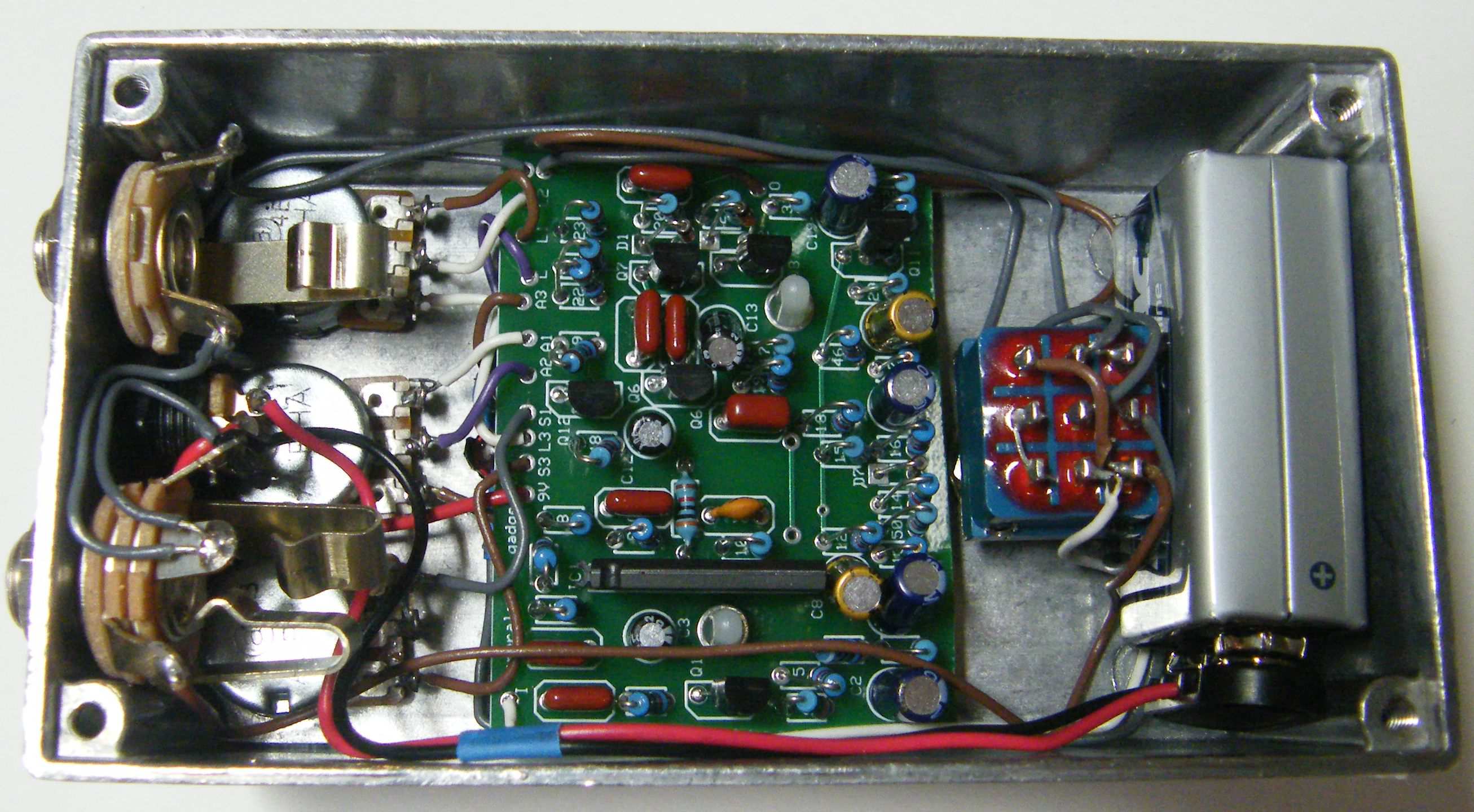
This is a replica of the IbanezTM BP10TM Bass Compressor. This is an excellent bass compressor. Use the project documents provided, starting with the General Build Instructions. Notice that nearly all the resistors are standing on end. View the inside photo below to see how to install the resistors.
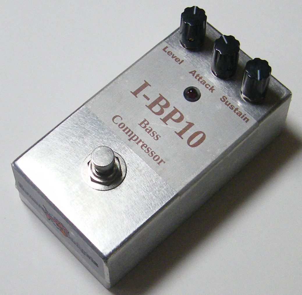
Here's an inside view of the unit we built.
Here is a chart of voltages taken at the transistor pins. This information can be used to help you find and fix problems if your stompbox doesn't work when you test it.
Component
Location
9 volt power supply IC1
Q1
Q6
Q7
Q8
Q11
Voltage
9.4
4.0v
4.7v
Pin 2
4.7v
Pin 3
0.07v
Pin 4
1.0v
Pin 5
0v
Pin 6
4.5v
Pin 7
4.5v
Pin 8
4.6v
Pin 9
9.4v
Collector
9.4v
Base
0.6v
Emitter
0v
Collector
7.0v
Base
3.0v
Emitter
2.4v
Collector
9.3v
Base
0v
Emitter
0v
Collector
9.3v
Base
0v
Emitter
0v
Collector
9.4v
Base
4.2v
Q12
Emitter
3.8v
Collector
9.4v
Base
9.2v
Emitter
8.8v
Comments and questions are welcome and can be sent to [email protected]
More about this project
Notes, sounds and related links


Ready to build? We have the kit.
Buy a BP10™ Complete Kit. Includes all the parts and materials you need to build one, all for about the price you would pay for a PCB and parts.
Would you like a Ready to Solder Circuit Board for this project?