
Project · Modulation/Echo
PT-80 Delay
A digital delay project from Scott Swartz. This is an awesome delay/echo stompbox that has received great reviews from the DIY stompbox community! Page down for sound samples.
Project files
Everything you need to build it
PT-80 Delay Ready-For-Transfer Printed Circuit Board Layout PDF File - For use only if you are a complete DIY person who wants to etch and drill your own PCB. Otherwise, we recommend you ignore this PCB mask and buy the Ready-to-Solder Printed Circuit Board or Complete Kit.
Parts layout
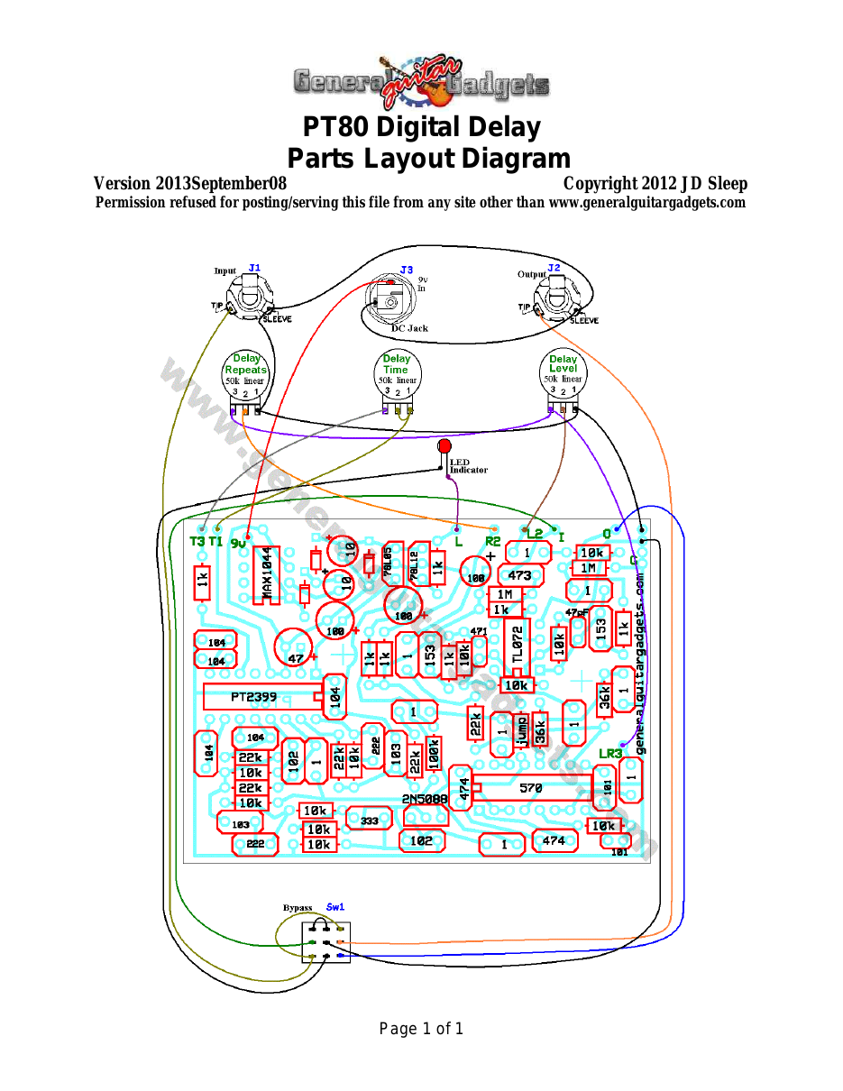
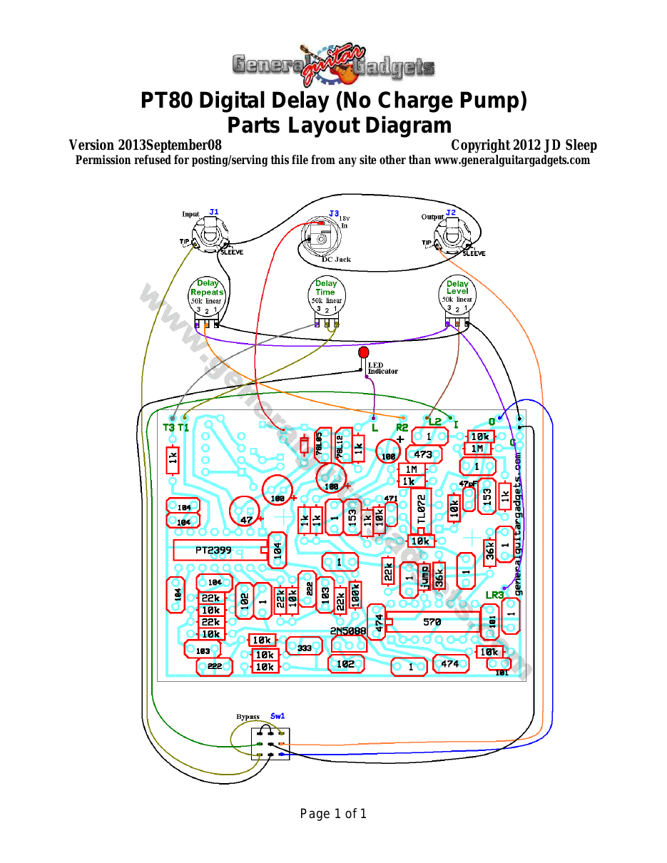
Parts Layout / Wiring Diagram
What you will need
Bill of Materials
Version 2012May09 · Copyright 2009 JD Sleep · Permission refused for posting/serving this file from any site other than www.generalguitargadgets.com · Trademarks are property of their owners
Resistors
| Component | Value | 3-band Marking | 4-band Marking |
|---|---|---|---|
| Count | |||
| 7 | 1k | brown-black-red | brown-black-black-brown |
| 11 | 10k | brown-black-orange | brown-black-black-red |
| 5 | 22k | red-red-orange | red-red-black-red |
| 2 | 36k | orange-blue-orange | orange-blue-black-red |
| 1 | 100k | brown-black-yellow | brown-black-black-orange |
| 2 | 1M | brown-black-green | brown-black-black-yellow |
Capacitors
| Component Count | Value | Type | Possible Marking |
|---|---|---|---|
| 1 | 47pF | Ceramic or Film | 470 |
| 2 | 100pF | Ceramic or Film | 101 |
| 1 | 470pF | Ceramic or Film | 471 |
| 2 | 0.001µF | Film | 102 |
| 2 | 0.0022µF | Film | 222 |
| 2 | 0.01µF | Film | 103 |
| 2 | 0.015µF | Film | 153 |
| 1 | 0.033µF | Film | 333 |
| 1 | 0.047µF | Film | 473 |
| 5 | 0.1µF | Film | 104 |
| 2 | 0.47µF | Film | 474 |
| 10 | 1µF | Film | 105 |
| 2 | 10µF | Aluminum Electrolytic | 10uF |
| 1 | 47µF | Aluminum Electrolytic | 47uF |
3 100µF Aluminum Electrolytic 100uF
Potentiometers
| Part ID | Value | Type |
|---|---|---|
| Delay Time | 50k | Linear Taper |
| Delay Level | 50k | Linear Taper |
| Repeats | 50k | Linear Taper |
Other
| Component Count | Part Name |
|---|---|
| 1 | TL072 or similar dual opamp (Kit does not include a socket for this IC) |
| 1 | NE571N or SA571 Compander |
| 1 | PT2399 Delay IC |
| 1 | MAX1044 Charge Pump |
| 3 | 1N914 |
| 2 | 8 pin socket (optional) |
| 2 | 16 pin socket (options) |
| 1 | LED |
| 1 | 2N5089 or 2N5088 |
| 1 | 78L05 (5 volt regulator) |
| 1 | 78L12 (12 volt regulator) |
| 2 | Mono quarter-inch jack |
| 1 | DC Jack |
| 1 | Heavy Duty 3PDT foot switch Printed Circuit Board, 24 gauge stranded wire, Enclosure, Knobs |
How to build it
Instructions
Version 2015June22 · Copyright 2007, 2014 JD Sleep · Permission refused for posting/serving this file from any site other than www.generalguitargadgets.com · Trademarks are property of their owners
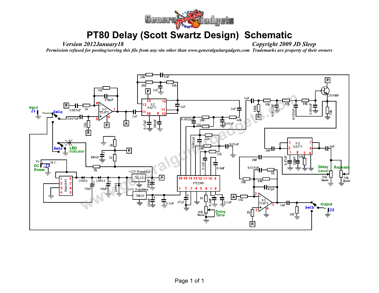
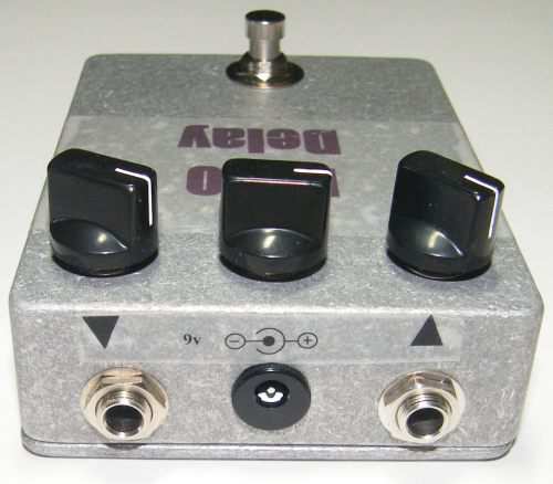
This is the famous DIY PT-80 Digital Delay by Scott Swartz. The idea here is to emulate the “old-time” analog delay unit, in this case the Ibanez™ AD-80 vintage stompbox, with a modern digital delay IC. The results are excellent and you won't be able to tell that it's not 100% analog. The general design of this circuit is almost the same as the AD-80 except the bucket brigade ICs are replaced with a Princeton Technologies PT2399 delay/echo IC and the electronic switching is replaced by a 3PDT stomp switch. The compander IC gives it excellent noise specs and also contributes to the great analog-like sound. A charge pump is on board so that it has plenty of headroom being powered from a typical nine volt power supply. The charge pump was not part of the original AD-80, but is a modern bonus in this project enable it to use a typical 9v Boss™ style stompbox wallwart power. It is not feasible to use a 9v battery, unless you just want to run it for about 10 minutes or less before the new battery goes dead. Note that since there is no battery, the input jack is a typical mono jack. Use the project documents provided, starting with the General Build Instructions. There are some options for power, if you have a 15 or 18 volt DC power supply and want to use it to power the PT80, you don't need the charge pump and it can be omitted. There is a parts diagram listed on the site if you want to build it without the charge pump circuit and plug 15 to 18 V DC directly into it.
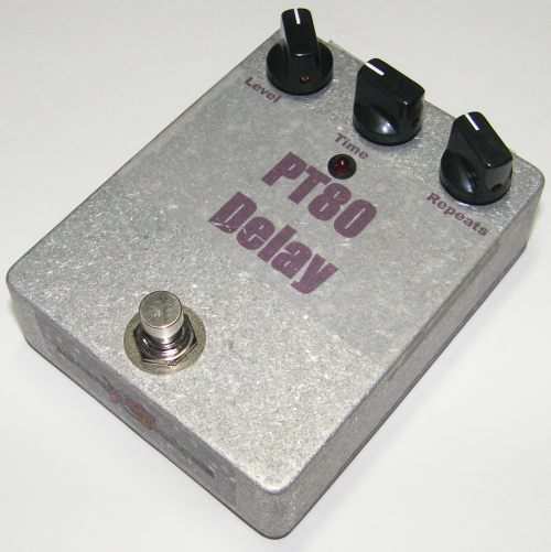
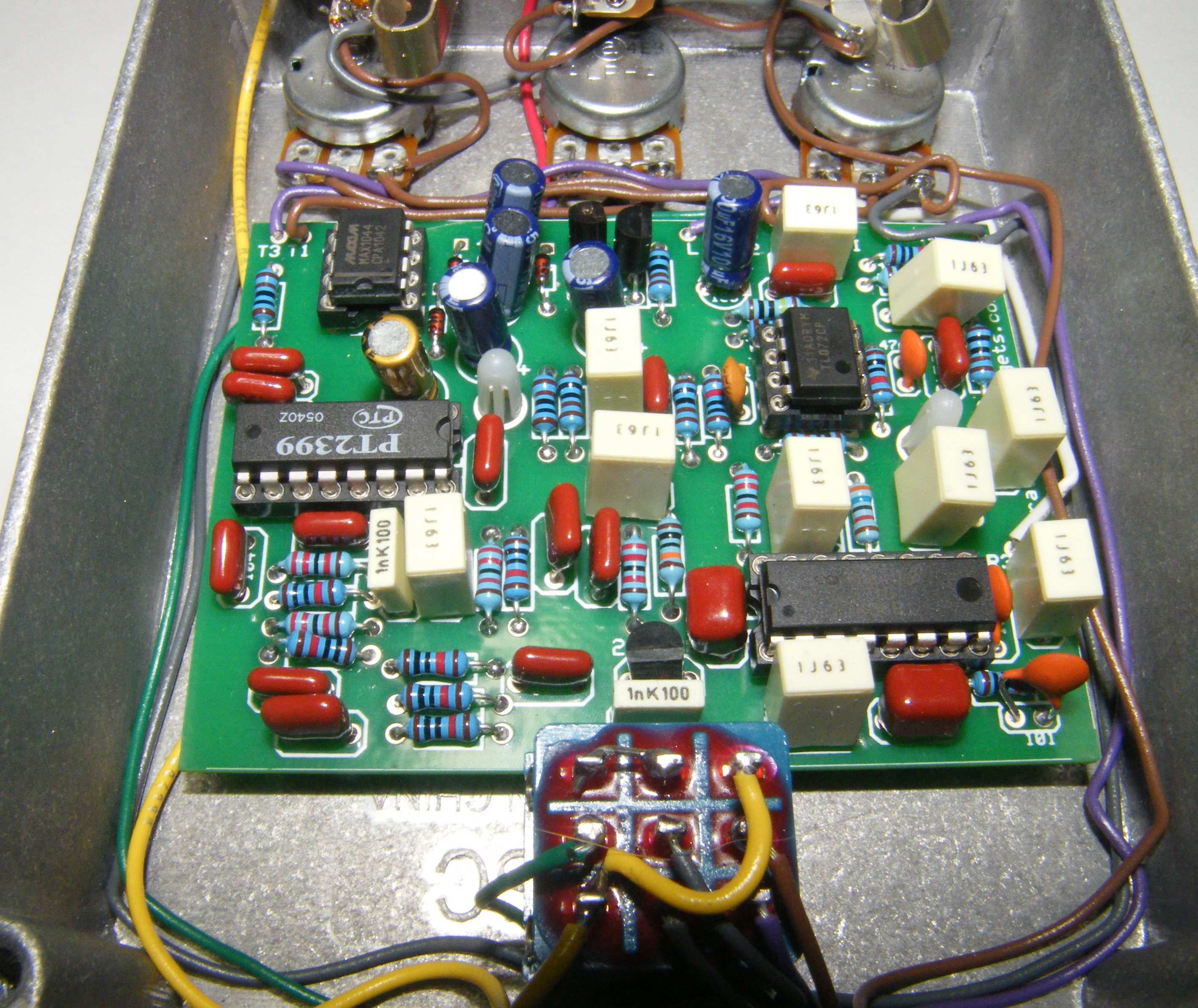
The kit comes with the MAX1044 Charge Pump IC. This unit will also run on 9v without the charge pump and if you put a jumper in place of the 12 volt regulator. We don't recommend this. It sounds "okay" running on 9 volts, but it really should run above 12v for the best sound. The AD-80 runs at 12v and has a 2-battery compartment, so to retain the "80" in the name, 9 volts power into the circuit is not quite right! Here's an inside view of the unit we built to to show the completed stompbox. The kit includes the charge pump and regulators so that you can run at 12 volts from 9v power. Note that the capacitors in your kit may not match exactly to the photo. The Kit comes with IC sockets for all the ICs.
Here are some voltage readings in case you have any problems and need to check. To check if the charge pump is working correctly, the voltage on the “top legs” (leg near the top edge of the PCB) of both regulators should be at about 16 volts. The “bottom legs” of the regulators should be 12 volts and 5 volts.
Component
Location
9 volt power supply TL072 IC
PT2399 IC
Voltage
9v
IC Pin 1
6v
IC Pin 2
6v
IC Pin 3
6v
IC Pin 4
0v
IC Pin 5
5.5v
IC Pin 6
6v
IC Pin 7
6v
IC Pin 8
12v
IC Pin 1
5v
IC Pin 2
2.5v
IC Pin 3
0.015v
IC Pin 4
0.015v
IC Pin 5
2.8v
IC Pin 6
2.5v
IC Pin 7
0.9v
IC Pin 8
0.9v
IC Pin 9
2.5v
IC Pin 10
2.5v
IC Pin 11
2.5v
IC Pin 12
2.5v
SA571 IC (NE571, etc)
IC Pin 13
2.5v
IC Pin 14
2.5v
IC Pin 15
2.5v
IC Pin 16
2.5v
IC Pin 1
1v
IC Pin 2
1.8v
IC Pin 3
1.8v
IC Pin 4
0.003v
IC Pin 5
1.8v
IC Pin 6
6.5v
IC Pin 7
6.5v
IC Pin 8
1.8v
IC Pin 9
1.8v
IC Pin 10
6.0v
IC Pin 11
1.8v
IC Pin 12
1.8v
IC Pin 13
12.0v
IC Pin 14
1.8v
IC Pin 15
1.8v
IC Pin 16
1.0v
Comments and questions are welcome and can be sent to [email protected]
More about this project
Notes, sounds and related links


PT-80 Sound Files
copyright 2002 by Scott Swartz. All rights reserved
Introduction
After all the blah blah about how the PT-80 sounds like an analog delay, I threw together a few mp3's to illustrate. The recording signal chain is guitar amp to Royer R-121 ribbon mic (expensive but worth it) to homebrew tube mic preamp to mixer (EQ bypassed) to Tascam CD Burner. The guitar is a 62 RI Strat™, set to middle and bridge pickups. Amp is a homebrew Twin Reverb type circuit set for a clean sound with a bit of the onboard spring reverb.
The files give a general idea about the sound, but mp3 limitations wash out some of the very fine detail in the sound. You will definitely hear that it doesn't sound like a typical digital delay though.
Hear the Sound Files
Sound File 1 - The Rockabilly Slapback
This is a short passage that starts with a few notes without the delay. I switch it in the delay, and play another single note passage, then conclude with a little Travis picking riff.
Control Settings are: Delay Time = 30%, Repeats = 25%, Delay Level = 50%.
Sound File 2 - The 175 Millisecond Atmospheric Delay
This is a sample of how I typically use delay, set for about 175 ms, 3-4 repeats, and the delay level set to give some atmosphere behind the notes. I play a thirds and sixths riff all the way though, then kick in the delay and play the passage again.
Control Settings are: Delay Time = 40%, Repeats = 30%, Delay Level = 40%.
Sound File 3 - The Maximum Delay Playing Notes For You Sound
This is a passage to demonstrate the sound quality of the repeats when set to max delay (using a 50K pot). The delay level is turned up to match the volume of the dry signal, and then I play a few descending sixths in time with the repeats to create a big wash of sound. At the end, I play a couple of single notes to isolate the repeats sound. The higher note does have some distortion, this isn't present at shorter delay settings.
Control Settings are: Delay Time = 100%, Repeats = 30%, Delay Level = 60%.
Ready to build? We have the kit.
Buy a PT80 Complete Kit. Includes all the parts and materials you need to build one, all for about the price you would pay for a PCB and parts.
Would you like a Ready to Solder Circuit Board for this project? Note: If you buy the kit, the Ready-to-Solder Printed Circuit Board (RTS PCB) is included in the kit. You do not need to purchase this Ready to Solder Circuit Printed Board if you buy the kit.